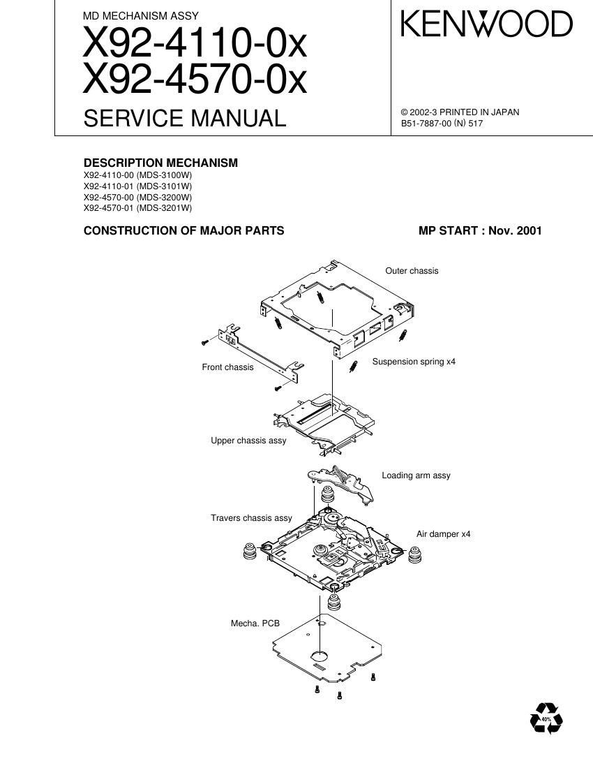
Kenwood X 92 4570 0x Service Manual

This is the 33 pages manual for Kenwood X 92 4570 0x Service Manual.
Read or download the pdf for free. If you want to contribute, please mail your pdfs to info@audioservicemanuals.com.

Page: 1 / 33
left right
Kenwood X 92 4570 0x Service Manual

Extracted text from Kenwood X 92 4570 0x Service Manual (Ocr-read)


Page 1

X92-4110-0x/4570-0x 2 BLOCK DIAGRAM RF AMPRF AGC & EQIC1 BPF P-P PEAK & BOTTOM ABCD AMP IV AMP IV AMP CVB AMP TEMP VICCONVERROR AMP FOCUS AT AMPBPF TRACKING ERROR AMP SERIAL PARALLEL DECODER BALANCE E-F FILTER PLL DECODER ACIRC EFM MEMORY RESISTANT SHOCK CONTROLLER DYNAMIC RAM ATRAC/ATRAC3 DECODER DIGITAL FILTER CONVERTERD/APOST FILTER CONTROL MONITOR ANALOG MUX ADIP DEMODULATOR DECODER SPINDLE SERVO GENERATOR PWM APCDSP SERVO CONVERTER A/D CLOCK GENERATOR AUTO SEQUENCERI/F CPU PROCESSOR SUBCODEIC7 MECHA MI-COM CH2 DRIVER CH1 DRIVER DRIVER CH4 DRIVER CH3 VREF DRIVER CH5IC5 LOE/LIM-SW LOS/EJE-SW ATRAC/ATRAC3 DECODER DET. REFLECT APC CB DAF EJ IDETECTOR TRACKING COIL FOCUS COIL M LOADING/EJECT/SLED MOTOR SPINDLE MOTORMTHERMISTER IC9 256 SW+5V EFM/ACIRC DECODER SHOCK PROOF MEMORY CONTROLLER DIGITAL SERVO PROCESSOR DIGITAL SIGNAL PROCESSOR 1M-WORD 4BIT DYNAMIC RAM DIGITAL FILTER. D/A CONVERTER IC2 FOCUS/TRACKING COIL DRIVER SPINDLE/SLED MOTOR DRIVER IC4 LOADING/EJECT MOTOR DRIVER REG. A3.3V IC6 A. 8V SW8BIT Q8 IC11 IC10 2.5V REG. IC3AUDIO I/F DIGITAL Q1,2 5ch BTL DRIVER Q4 RF AMP Q3DSP LPF IC8 Q7 Q5,6,9 1 2 4 5 6 7 8 9 3 15 14 I J A B C D E F 11 12 22 23 25 41 42 19APC APCREF EQADJ 3TADJ WBLADJ FZC RF AUX1 AUX2 PEAK BOTTOM ABCD FE VC SWDT SCLK XLAT FOCONT 114 113 84 85 77 76 112 111SPFD SPRD FFDR FRDR TFDR TRDR SFDR SRDR 25 28 5 15 21 20 MNT0 MNT1 MNT2 MNT3 XINT SQSY SENS SRDT SCLK SWDT XLAT XRST44 45 46 62 18 20 19 17 16FZC XINT SQSY SENS SRDT SCLK SWDT XLAT XRST 12 56 23 11 15 13 14 43 36 59 60LDON SDMUTE LIMIT SW P-ON AMUTE MSDA MSCL MSTOP MRST TYPE 1 TYPE 2 33 7 8 HOT ESDA ESCL 20 19 17 16 30 29 23 22 26 25 24 TRK+ TRK- FCS+ FCS- LOAD/SLED+ EJECT/SLED- SPDL+ SPDL- VC VREF0 VCC2 VCC1 10 11 12 13 7 6 8 9 28 27 3 14TFDR TRDR FFDR FRDR LOAD/SFDR EJECT/SRDR SPFD SPRD REG IN REG OUT ENREG1 11 9 14 13 20 19 15 18 5 6 2 21 7 8DOUT L-CH R-CH MRST MSTOP MSCL (IIC BUS) MSDA AMUTE BU5V S5V S5V LOE/LIM-SW LOS/EJE-SW LOAD EJECT 36 30 29 31 34 35 37 33 38 47 46 48 40 1028 26 32 17 18 20 27 16 41 40 MORF RFO AUX 1 FOCONT XSTBYADFG 22.579MHz 6 7 8 35 16 14 13 10 9 11 104 105 106 107 102 84 93 80 81 82 83 67 73 72 71 70 85 92 915 11 13 3 1 122 106 48.388MHz MUTE 1 MUTE 2 1 2 MUTE 336CH1,2 CH3 CH4 21 67 JITTER RECORD IN VC TE SEVC VC VC VC PD LD STBY TO CH5 OP S+B SW+5V S5V +3.3V6 5 BU+5V1.2Vrms 1kHz 0dB SW+5V TO SERVO DRIVERBU+5V ILCC LDON AUDIO +BDAVDD SW+5VA8V 12 34 +2.5V MOTOR ASSY DPU1 OPTICAL PICKUP BLOCK MOTOR BLOCKMD UNIT BUFFER

Page 2

3 Ref.No. Component name Application/Function Operation/Condition/Compatibility RF amplifier(pits and groove selector type, AGC, EQ), Gain selector type I-V amplifier, Amplification of the light intensity signal output, IC1 CXA2523AR RF amplifier for MD Peak hold output, Bottom hold output, FE output, TE output, SE output, ADIP binary output, VREF output, APC PD amplifier and FZC formation comparator. EFM decoding, EFM digital PLL, ACIRC decoding, auto link IC2 CXD2667R Digital signal processor for MDprocessing, ADIP decoding, Digital ser vos(focusing, tracking, sled, spindle CLV), ATRAC/ATRAC3 decoding, 1 bit D/A converter, Analogue post filter and 4M(1Mx4) DRAM built in. IC3 S-817A25ANB +2.5V AVR Power supply for IC2 internal logic circuits. IC4 LA6572 5 Ch BTL dr iverFocusing coil, tracking coil, spindle motor and sled motor driver, disc loading and eject operation. IC5 NJM4580M1 Low pass filter 2nd low pass filter for audio signals. IC6 LP2982-3.3 A.3.3V AVR Power supply for DAC and LPF operational reference voltage. IC7 TC74HCT7007AF Buffer Buffer and logic level conversion from IC1,2 to IC8. IC8780076YGK-R11 Mecha.MI-COM. Servo control, memory control, system control and interfacing. (X33-3160-00) IC8780076YGK-R14 Mecha.MI-COM.Servo control, memory control, system control and interfacing. (X33-3180-00) Adapted to MD Group. IC9 W05-0906-00 EEPROM Servo coefficients and servo adjustment data backup memory IC10 TC7WH126FU 3-State bufferWhen 1, 7 pin goes Hi, Sled ser vo operation is selected. When 1, 7 pin goes Lo, IC10's outputs is Hi-Z operation. IC11 TC7WH126FU 3-State bufferWhen 1, 7 pin goes Hi, Loading/Eject operation is selected. When 1, 7 pin goes Lo, IC11's outputs is Hi-Z operation. Q12SA1362(Y) or APC(Auto Power Control) LD power control 2SB1295 Q2DTA114EUA or LD SWWhen Laser OFF mode is selected, Q2's base goes Lo, and Q1 is KRA302 or UN5111 tur ned off. Q3 2SC4116(Y) Disc refrection detect SW On when focusing point is passed during upward search. Q4 MCH6101 D.3.3V AVR driverWhen Loading/Eject operation or MD source is selected, Q4's output is supplying D.3.3V to IC1-3, IC10 and IC11. Q5 DTA143XUA When SW5V SW is turned on, Q5 and Q6 are tur ned on, and A.+8V Q6DTC143EUA or A.8V SW is supplying to A.3.3V AVR and low pass filter circuit. KRC401 KTA2014(Y,GR) or When MD source is selected, P-ON output goes Lo, and BU5V is Q7 2SA1576A or SW5V SW supplying to microprocessor peripheral circuits and A.8V SW. 2SB1218A Q8DTC143EUA or IC10 OUTPUT Hi-Z SWWhen Loading/Eject operation is selected, Q8's base goes Hi, and KRC401 IC10's outputs is Hi-Z operation. Q9DTC143EUA or A.8V SWWhen Loading/Eject operation is selected, Q9's base goes Hi, and KRC401 A.+8V is supplying to A.3.3V AVR and low pass filter circuit. X92-4110-0x/4570-0x MD UNIT(X33-3160/3180-00) COMPONENT DESCRIPTION