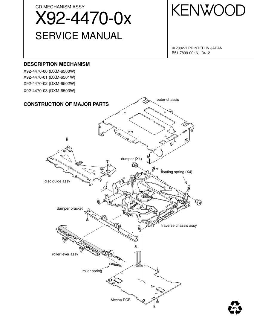
Kenwood X 92 4470 00 Service Manual

This is the 20 pages manual for Kenwood X 92 4470 00 Service Manual.
Read or download the pdf for free. If you want to contribute, please mail your pdfs to info@audioservicemanuals.com.

Page: 1 / 20
left right
Kenwood X 92 4470 00 Service Manual

Extracted text from Kenwood X 92 4470 00 Service Manual (Ocr-read)


Page 1

X92-4470-0x 2 BLOCK DIAGRAM Mother Board IC10IC12 Pick-UpR-ch L-ch 7IC6 A.GND A Q2 CIC11 Q4 9Q5D.GND Vref D.GND IC5 Q1 D.GND D.GNDSW5V /PON Bu.+5V Q3 IC2 X2X3 D.GND 916 IC3 IC416.93MHz S3 Loe/Lim SW IC8 S4 8Eje SW S2 12Eje SW S.GND D.GND S1 D.GND Los SW S.GND D4.7V D3.3VReg Fo CoilTr CoilA.+8V Loading & Sled Motor Spindle MotorSW PON 2.5V Reg Motor DriverSW SW Motor S7.5V Lo/Ej 0-01 Only A.GND A.GND A3.3 Reg E APC µ-Com DRAM8V SW 1Chip IC Servo Processor + RF Amp + MP3 Decorder WMA Decorder LPF Clock 16.93MHz Clock 24.57MHz F 30 B D CD PLAYER UNIT (X32-5220-0x) Ref.No. Application/Function Operation/Condition/Compatibility IC2 D3.3V AVR Power supply for the pickup, IC5, IC8-10 and IC11 IC3 D2.5V AVR Power supply for IC8 IC4 4CH BTL dr iverFocusing coil, tracking coil, spindle motor and sled motor driver, disc loading and eject operation. IC5 Mecha. control MI-COM. IC6 A3.3V AVR Power supply for DAC, LPF operational reference voltage IC7 Level shifting (3.3V-†’5V) Buffer and logic level conversion from IC10 to IC5 IC8 WMA decoder IC9 Clock buffer for WMA IC10 RF amplifier+CD DSP+MP3 decoder IC11 4M bit DRAM For data buffer IC12 Low pass filter 2nd low pass filter for audio signals IC13 Schmitt tr igger for WMA Q1 SW5V SWWhen PON (11pin) goes Lo, Q1 is turned on, and SW5V is supplied to IC7 and AVREF (73PIN). Q2 APC LD power control Q3 D3.3V SW When PON (10pin) goes Hi, Q3 is turned on, and IC2 is working. Q4 A.8V SWWhen PON (10pin) goes Hi, Q4 and Q5 are turned on, and A.8V is supplied to IC6 Q5 and IC12. COMPONENTS DESCRIPTION

Page 2

X92-4470-0x 3 MICROCOMPUTERS TERMINAL DESCRIPTION processing Pin Name I/O Purpose Processing operation description description in STBY 1~5 NC O Not use Low fixation Low 6 VDD - 5V potential 7 GND - GND potential 8,9 NC O Not use Low fixation Low 10 PON O Power ON/OFF control H : ON L : OFF Low 11 /PON O Power ON/OFF control H : OFF L : ON High 12 LOE/LIM_SW I Down limit SW detection L : inside circumference detection Hi-Z 13 8EjE_SW I Not use Low fixation Hi-Z 14 LOS_SW I Not use Low fixation Hi-Z 15 12EjE_SW I Not use Low fixation Hi-Z 16,17 NC O Not use Low fixation Low 18 IC/Vpp - Writing voltage (FLUSH) - 19 MUTE_L O Lch audio mute control L : mute ON H : mute OFF Low 20 MUTE_R O Rch audio mute control L : mute ON H : mute OFF Low 21~25 NC O Not use Low fixation Low 26 EFLG I WMA error detection H : error L : not error Out-Low 27 WAIT I Weight control signal detection Out-Low 28 FOK I Focus condition detection H : Focus OK L : Focus NG Out-Low 29,30 NC O Not use Low fixation Low 31 RESET I Reset detection H : normal L : reset Hi-Z 32 XT1 I Not useHi-Z 33 XT2 - Not use- 34 REGC - 35 X2 - 36 X1 IHi-Z 37 Vss - GND potential 38 VDD - 5V potential 39 NC O NC Output stop Low 40 WRL O Multiplexer WRITE signal _LBEN : 61002 (not use) _WRL : 63760 Out-Low 41 NC O Not use Low fixation Low 42 R/W O Multiplexer _R/W signal _R/W : 61002 _WRH : 63760 (not use) Out-Low 43 DSTB,RD O Multiplexer DSTB or RD signal _DSTB : 61002 _RD : 63760 Out-Low 44 ASTB O Multiplexer ASTB signal Out-Low 45,46 NC O Not use Low fixation Low 47~54 AD0~7 I/O Multiplexer address/data Out-Low 55 BVdd - Power supply for bus inter face 56 BVss - GND for bus inter face 57~64 AD8~15 I/O Multiplexer data/address Out-Low MECHANISM MICROCOMPUTER (IC5 : X32)

Page 9

X92-4470-0x 10 OPERATION DESCRIPTION (5) Floating position and lock position of the mechanism The disc is loaded and ejected by rotation of the rollers that come in close contact with the disc. After the disc has been pulled in by the rollers, its position should be adjusted so that it can be placed precisely on the turntable of the traverse chassis. To make this possible, the traverse chassis and outer chassis should be in the locked condition. Since the outer chassis is originally locked on the main unit, if the traverse chassis is also locked during playback, the disc would be subjected directly to vibrations of vehicle during driv- ing and the disc signal would be hindered, making the audio intermittent or impossible to be played. To prevent such a problem, the traverse chassis is suspended from the outer case using springs or rubber dampers during driving. This positioning protects the disc playback operations and is referred to as the floating position. (6) Function of slider (L) Slider (L) ensures the mechanism lock position because the shafts of the outer chassis are inserted into its grooves in the same way as they are inserted into the grooves on slider (R). As slider (R) moves, the force moving the roller lever is transmitted to slider (L), which also star ts the sliding movement. When the spring is compressed gradually to a cer tain point, the force changes to a reverse force, which sup- ports the jump-up operation of the roller lever. Shafts for locking the traverse chassis (Outer case-integrated design) (4 shafts) Outer-chassisThe shafts of the outer chassis are inserted into the grooves on the sliders. Outer-chassis Traverse chassisSlider Outer-chassis The shafts of the outer chassis are inserted into the grooves on the sliders. Spring Roller lever Reverse force The shafts on the outer chassis are disengaged from the grooves on the slider.Mechanism floating position Mechanism lock position Mechanism lock position Mechanism floating position