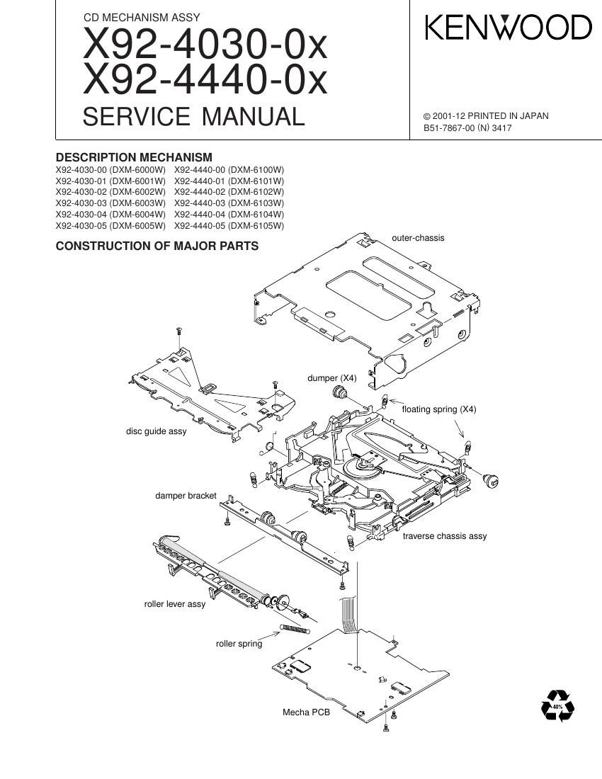
Kenwood X 92 4030 00 Service Manual

This is the 18 pages manual for Kenwood X 92 4030 00 Service Manual.
Read or download the pdf for free. If you want to contribute, please mail your pdfs to info@audioservicemanuals.com.

Page: 1 / 18
left right
Kenwood X 92 4030 00 Service Manual

Extracted text from Kenwood X 92 4030 00 Service Manual (Ocr-read)


Page 2

X92-4030-0X
X92-4440-0X

NOTE FOR HANDLING MECHANISM ASSY

N Pick is under the finger, it N Dont touch the lever be- N Don't have the center of
may touch. cause the trigger lever entrance because the disc
comes off. insertion mouth is trans-

formed.

PICK Up - Don't touch in the frame, since grease is
applied to the parts.

SPINDLE MOTOR - Don't applied grease to the roller.
- Don't touched PICK and SPINDLE MOTOR.

ROLLER

Page 3

X92-4030-0X

BLOCK DIAGRAM X92'4440'0X

Mother Board

pour 22
77777 x1 (CLK 19
(Down; 4 DATA 1a
" 16.93MHZ (MSTOP 1o
ic1 ic2 (MRST 11
5 2 IMUTEL 12
< ' [IMUTE R] 13
Q1 RFAmp 11 lCG
L-ch a
AFC V3, LPF R-ch 6
i 1Chip|C
Servo Processor
. A.+8V 9
Mi-com
I A.GND 7
ic4
2 Ver
TrCuil
2
FnCoil h MUTE DRVMUTE Bu.¢5V 15
MolurDriver 7
SpindieMmor H9
Lodin H 11an 14
L03 g&Sled 2 -
Mumr V . Vraf
E13 L Lue/Lim sw1
anesw 17
12511: SW 21
Lossw 20
57.5v 3
o- S.GND 2
Motor 4
Lo/Ej 5

COM PONENTS DESCRIPTION

.CD PLAYER UNIT (X32-5170-0x/X32-5190-0X)

Rel.No. Application/Function Operation/Condition/Compatibility

Generation of RF and servo error (focusing error, tracking error)
signals based on the signals read from the APC circuit and
pickup, detection of dropouts, anti-shock, track crossing and off-
track signals, and gain switching for CD»RW.

Focusing, tracking, sled and spindle servo processing, automated
processing (focusing, tracking, gain, offset and balance), digital
ICZ CD signal processor LSI + Mechanism u-COM signal processing (DSP, PLL, subcode, CIRC error correction and
audio data interpolation),

Text function (MN662773kH2), and microcomputer function.
Drive of the focusing coil, tracking coil, sled motor and spindle
motor, plus loading and ejection operations.

ICI CD-RW compatible RF amplifier

|C4 4-CH BTL driver

IC6 Audio active filter Secondary LPF

01 For APC (Auto Power Control) LD drive.

02 Q3 SW ON when P-ON = "H" (when SW +5 V is ON).
Q3 A.8V SW ON when P-ON = H" (when 02 is ON).

Q4 D.5V SW ON when P-ON = "H" (when 05 is ON).

05 Q4 SW(P-ON) ON when P-ON = "H".

D1 Pickup laser diode protection

D2 D/A converter power supply diode A.8V -> A.5V

D3 For static protection

D4 For forced gain boost (tracking servo)

P»ON: Pin 82 of IC2.