Kenwood VRS 7200 Service Manual

This is the 30 pages manual for Kenwood VRS 7200 Service Manual.
Read or download the pdf for free. If you want to contribute, please mail your pdfs to info@audioservicemanuals.com.

Page: 1 / 30
left right
Kenwood VRS 7200 Service Manual

Extracted text from Kenwood VRS 7200 Service Manual (Ocr-read)


Page 1

VRSJZOO(K)INT1P( 05.3.4 9:43 «3? 1 \

AUDIO-VIDEO SURROUND RECEIVER

VHS-7200 KENWOOD

Kenwood Corporation
SERVICE MANUAL

© 2005-3 PRINTED IN KOREA
851-5945-00 (K/K) 1010

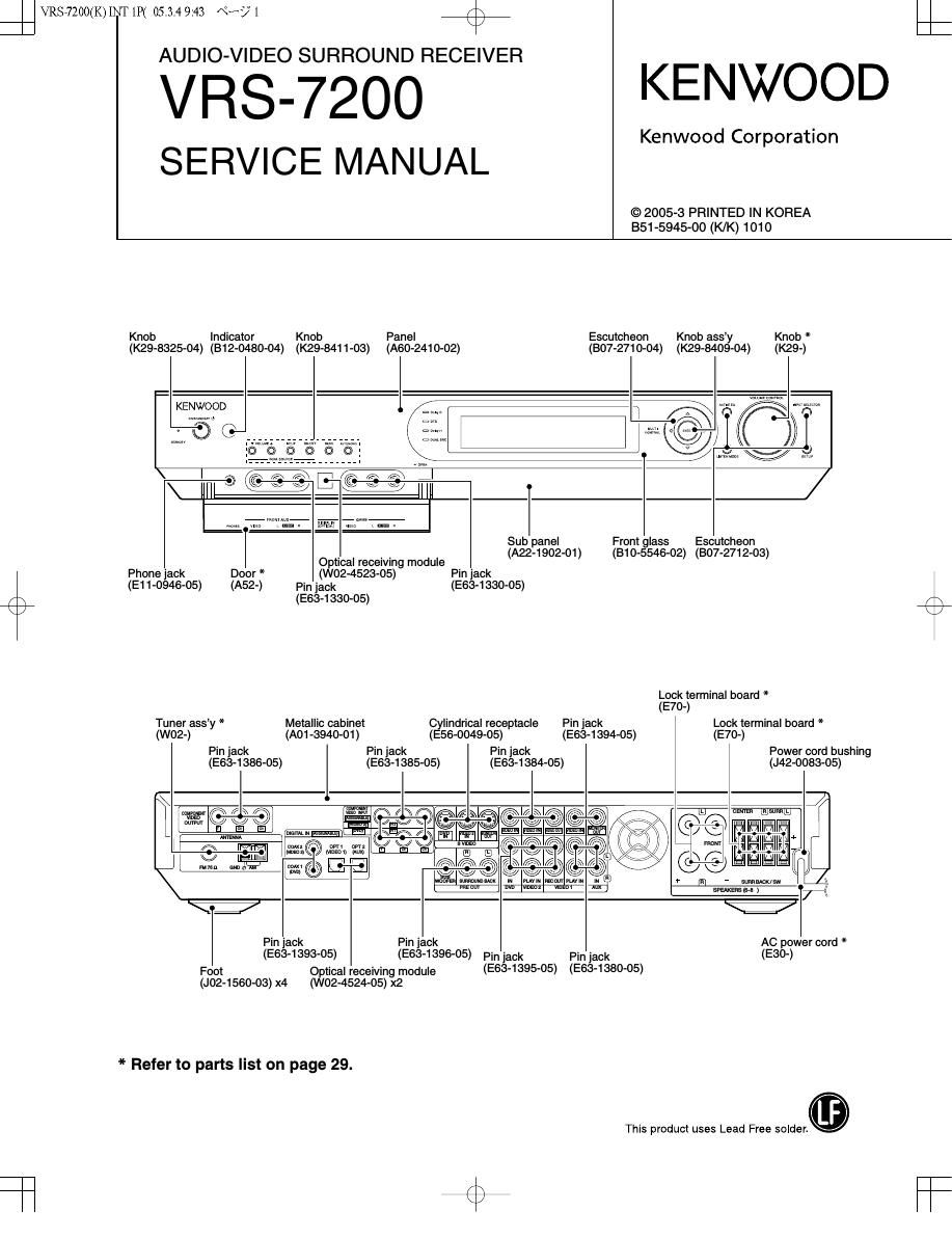
Knob Indicator Knob Panel Escutcheon Knob assy Knob *
(K29-8325-04) (B12-0480-04) (K29-8411-03) (A60-2410-02) (307-2710-04) (K29-8409-04) (K29-)

KENWOOD

A 7

7/
\ I II 3 ,
Sub panel Front glass Escutcheon
_ _ _ (A22-1902-01) (B10-5546-02) (307-2712-03)
Optical recelvmg module
Phone jack Door * (W02-4523-05) Pin jack
(E11-0946-05) (A52-) Pin jack (E63-1330-05)
(E63-1330-05)
Lock terminal board *
(E70-)
Tuner assy * Metallic cabinet Cylindrical receptacle Pin jack Lock terminal board *
(woe) (A01-3940-01) (E56-OO49-05) (E63-1394-05) (E70-)
Pin jack Pin jack Pin jack Power cord bushing
(E63-1386-05) (E63-1385-05) (E63-1384-05) (J42-0083-05)

\E

@I/NS 7 rm g
WV

Pin jack Pin jack AC power cord *
(E63-1393-05) (E63-1396-05) Pin jack Pin jack (E30-)
Foot Optical receiving module (E63'1395'05) (E63'1380'05)

(J02-1560-03) x4 (W02-4524-05) x2

* Refer to parts list on page 29.

This product uses Lead Free solder.

Page 2

VRSJZOO(K)INT1P( 05.3.4 9:43 «3? Z

VHS-7200

4%

ACCESSORIES / CAUTIONS

ACCESSORIES
r N
Remote control unit (1) AM loop antenna (1) FM indoor antenna (1)
RC-R0920 (A70-1677-05): KP (T90-0906-05) For Europe and Australia
FlC-R0920E (A70-1678-05): XE (T90-0175-05): XE
:32: 3
23:: E 3
Antenna adaptor (1)
(T90-0827-05)
Batteries (RB/AA) (2)
v For the U.S.A. and Canada
(T90-0905-05): KP
\ J
CAUTIONS

Resetting Ihe Mirraramputer

The microcomputer may malfunction (unit cannot be operated, or
shows an erroneous display) if the power cord is unplugged while
the power is ON, or due to some other external lactor. If this
happens, execute the following procedure to reset the microcom-
puter and return the unit to its normal operating condition.

Manufactured under license from Dolby Laboratories. "Dolby, "Pro
Logic, Surround EX" and the double-D symbol are trademarks of
Dolby Laboratories.

Unplug the power cord from the wall outlet, then plug it back in
while holding down the ONISTANDBY 0) key.

"DTS", "DTS-ES Extended Surround",
"Neo:6" and DTS 96/24 are trademarks
of Digital Theater Systems, Inc.

' Please note that resetting the microcomputer will clear the contents
of the memory and returns the unit to the state it was in when it left
the factory.

Page 11

VHS-7200


1x09234104 0|
_- CN7A
29722.2. won
E a >¥j FllAMEm
5.- mmw.
R955 cast
oNn
2.2 mm?
R SVH@ voD5MicoM
95 59 am: warm
2
#smv voDaMicoM
p1 m .2
242 z W.
73 @ ENC VOLCw cmol
2- 77 EchoLccw
> flail Km, 35> Elsa
I? «2&7 KEV S'IANDBV
has); REMOTE
Fam- LED stNpev
Amr@ s-us m
3 «22 suaMiso
2; 25 @suasnm
(as); suEMosI
mm- suacLK
my? suEMnEo
m cm 124:1
47 mo;
234v
x x )2 x x x x x
é § 5 § § § § § §
:2 Q E § E E E 3 E
a mum
Rsanuw > cN72
Magma E yum
Rszanw VCU
55" VST
Manna vchrMuTE
vcncwzovp
R925 1w 5 MUTE X25-AI2-
R925 mu 5 swz (:ng
Rsznoo SSW. |i5>
MW 3;; mm m
mam cvas sws @
My m 59 cvas swa
Rm @ cvas sw2
cvassw1
42» 35, 0 VDET
Wm 35" HPDEY
mum
>~
mam
Raaatm
Raanoo BEN - -
mm m CAUTION: For continued safety, replace safety crit-
kfl ® ical components only with manufacturer's recom-
§ § § 5 § E 5 g E g 5 mended parts (refer to parts list).A indicates safety
5 g g g g g g g g g g @ critical components. For continued protection
U @Q) 5% against risk of fire, replace only with same type and
43 CN7 rating fuse(s). To reduce the risk of electric shock,
% @ m leakage-current or resistance measurements shall
(9 be carried out (exposed parts are acceptably insu-
m FNEWi :33; lated from the supply circuit) before the appliance is
.9 12»
N55,__® mm returned to the customer.
4R© SLEVEL
he #49 mm:
2 A57);@ 5T: . . .
ASE)- 2 m The DC voltage Is an actual reading measured With
> 57 a high impedance type voltmeter with no signal
9 input. The measurement value may vary depending
5 on the measuring instruments used or on the prod-
an-z TAssHuTDowN uct
a2» TAsnsr -
as» 9 us an»: new
552- a TAsMurE
H555 au- mm
22 a. TAssoA
m TASSCL
5 DC PHD! X07-
VDD FAN 0N1
an? AuDlo CllSW/CS) Q
2252* m whims/E
- s GND
6 ,
05.?» 464»~ z Aunloua
7 am
595" A57>--~ 6 AUDlDECLK
2 .- 5 mm
->.sv>- aasp~ . AunloFcLK
.39v 3 mm
29.0- 2 AunloMcLK
_ r em,
___________________vns_425(1/5)
X08-3410-1O (3/3) 19
\ 7