Kenwood VR 606 Service Manual

This is the 23 pages manual for Kenwood VR 606 Service Manual.
Read or download the pdf for free. If you want to contribute, please mail your pdfs to info@audioservicemanuals.com.

Page: 1 / 23
left right
Kenwood VR 606 Service Manual

Extracted text from Kenwood VR 606 Service Manual (Ocr-read)


Page 1

VR7606(K)INT1P 02.3.26 4:26 PM NRA) 1 /\

AUDIO-VIDEO SURROUND RECEIVER KENWOOD
VR-606/ 61 6

SERVICE MANUAL

©2002-3 PRINTED IN KOREA
B51-5787-00 (K/K) 1383

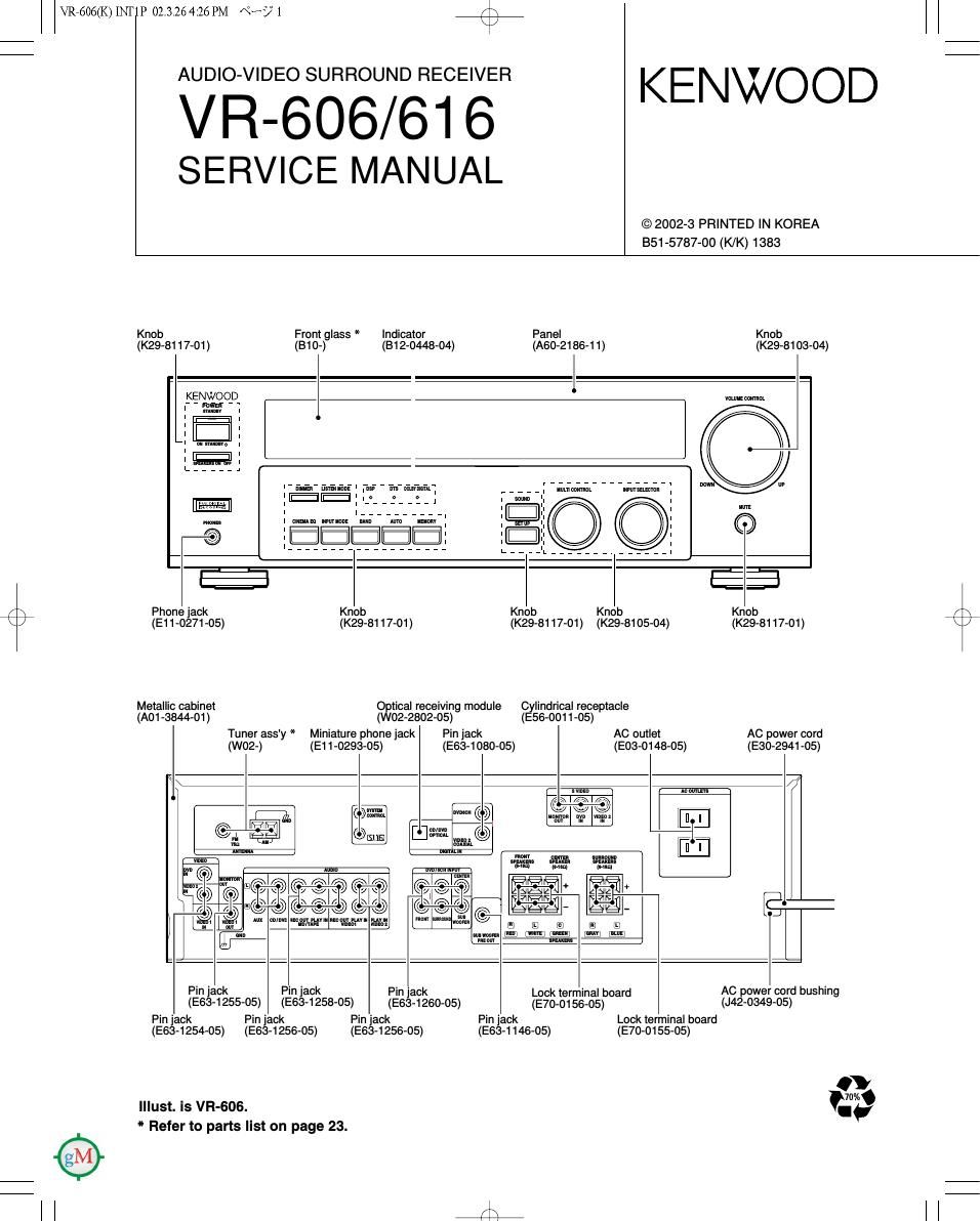
Knob Front glass * Indicator Panel Knob
(K29-8117-01) (B10-) (B12-0448-04) (AGO-218641) (K29-8103-04)
KENWOOD vmunsmimml.

,,,,, I mm mm wmsmm

©©

,,,,,,,,,,,,,, E

/ \ Phone jack Knob Knob Knob Knob
\ / (E11-0271-05) (K29-81 17-01) (K29-8117-O1) (K29-8105-04) (K29-8117-O1) \
Metallic cabinet Optical receiving module Cylindrical receptacle
(A01 -3844-01) (W02-2802-05) (E56-0011-05)
Tuner ass'y * Miniature phone jack Pin jack AC outlet AC power cord
(W02-) (E11-0293-05) (E634 080-05) (E03-0148-05) (E30-2941-05)
7
\ 5 main A: WYLEYS \

» 51m
; annual

3511110 41
n n

mm cams. mnouun
svaksns spam. erAxm
(mm (mm) 4. may

E + +


gal- E-

E} El 1)
mm, nsnl (mm: [1:le mm; (M
new! -smur -

QROO,

M
:1: mn rum mam ruv 1». rum
mm»: mm

Pi" 130k Pin 130k Pin jack Lock terminal board AC power cord bushing
(E634 255-05) (E634 258-05) (E634 260-05) (E70-0156-05) (J42-0349-05)
Pin jack Pin jack Pin jack Pin jack Lock terminal board
(E63-1254-05) (E63-1256-05) (E63-1256-O5) (E63-1146-05) (E70-0155-05)
0
' mVA
Illust. IS VR-GOG. I.

* Refer to parts list on page 23.

Page 2

VR7606(K)INT1P 02.3.26 4:55 PM \°-A/° 2

VR-606/616

CONTENTS / ACCESSORIES / CAUTIONS

Contents

CONTENTS / ACCESSORIES / CAUTIONS.
PARTS DESCRIPTIONS ...............................
PC BOARD ...................

SCHEMATIC DIAGRAM ..

OA'ODN

Accessories

E
P
S

XPLODED VIEW. ..
ARTS LIST ........... ..23
PECIFICATIONS .................................................... 29

Remote control unit (1)
RC-RO728

(T90-0852-05)
(A70-1584-05)

Battery cover(A09-1258-08)

AM loop antenna (1)

Batteries (RB/AA) (2)

FM indoor antenna (1)
(T90-0877-05)

r\
\/

Cautions

Resetting the Microcomputer

The microcomputer may malfunction (unit cannot be operated, or
shows an erroneous display) it the power cord is unplugged while the
power is ON, or due to some other external tactor. It this happens,
execute the following procedure to reset the microcomputer and
return the unit to its normal operating condition.

- Please note that resetting the microcomputer will clear the contents
of the memory and return the unit to the state it was in when it left
the factory

For the U.S.A. and Canada

Unplug the power cord from the wall outlet, then
plug it back in while holding down the POWER key.

Memory back up function

Please note that the tollowing items will be deleted from the unit's
memory if the power cord is disconnected from the AC outlet for
approximately 3 days.

- Power mode.

- Input selector settings.
- Picture output.

- Speaker ON/OFF.

- Volume level.

- BASS, TREBLE, INPUT level.
- Dimmer level.

- MD/TAPE settings.

- Listen mode setting.

- Speaker settings.

- SW RE-MIX ON/OFF.

- Distance setting.

- Input mode setting.

- Midnight mode setting.

- PRO LOGIC || mode setting.
- Broadcast band.

- Frequency setting.

- Preset stations.

- Tuning mode.

- CINEMA EQ ON/OFF.

- LOUDNESS ON/OFF.