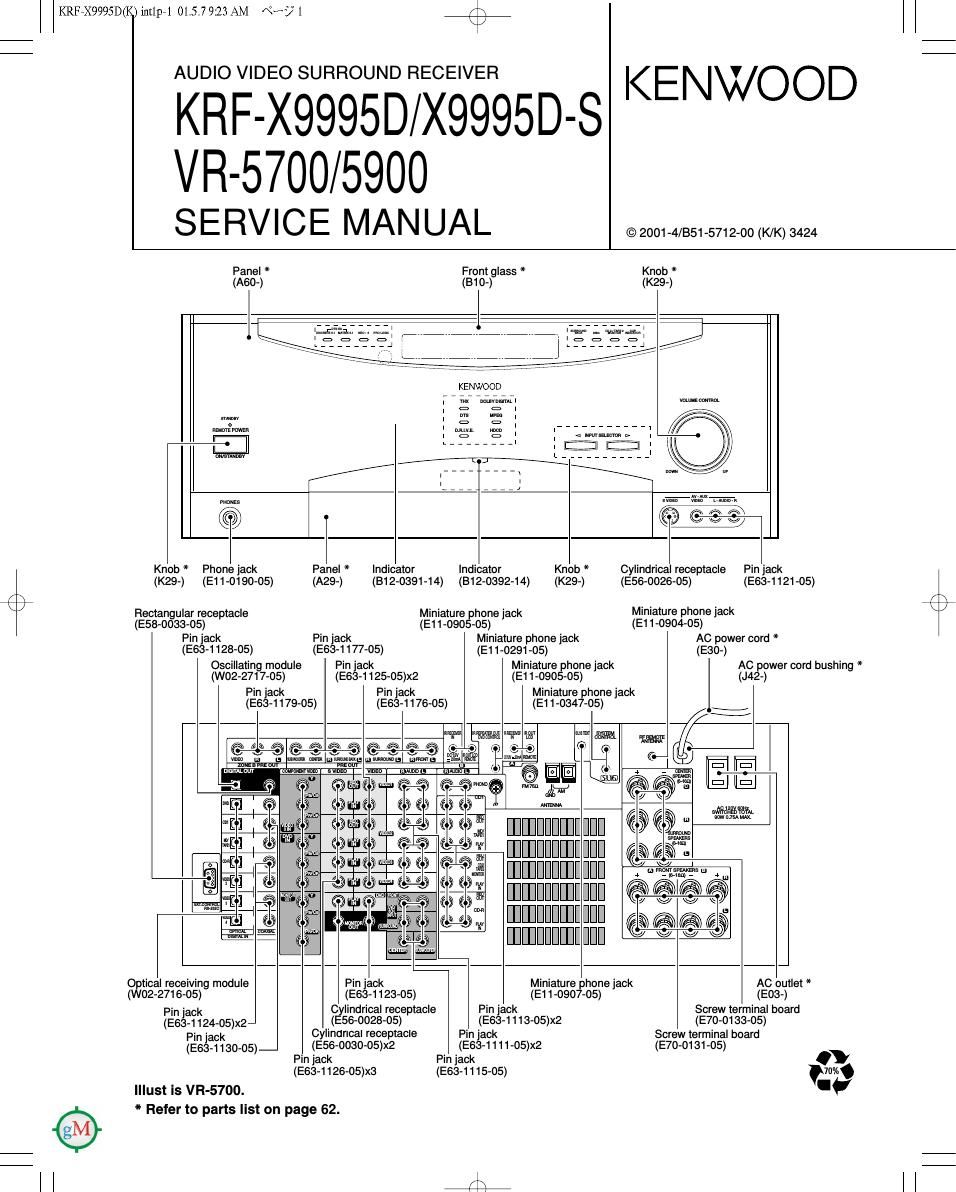
Kenwood VR 5900 Service Manual

This is the 71 pages manual for Kenwood VR 5900 Service Manual.
Read or download the pdf for free. If you want to contribute, please mail your pdfs to info@audioservicemanuals.com.

Page: 1 / 71
left right
Kenwood VR 5900 Service Manual

Extracted text from Kenwood VR 5900 Service Manual (Ocr-read)


Page 2

r\
\/

KRF7X9995D(K)iut1p71 01.5.7 9:23 AM N? 2

KRF-X9995D/X9995D-S/VR-5700/5900

CONTENTS / ACCESSORIES

Contents

CONTENTS / ACCESSORIES .................................. 2
DBASSEMBLYFORREPNR .m3
BLOCKDMGRAM ................. m5

PC BOARD .............................................................. 17
SCHEMATIC DIAGRAM 30
EXPLODED VIEW ............ ....60
...62

ADJUSTMENT ......... :.14 PARTS LIST ....... .
WIRING DIAGRAM.. ..... 16 SPECIFICATIONS ...88
Accessories
r

Remote control unit Batteries AM Loop Antenna FM Antenna

(A70-1453-05): FIC-FI091 3

E

Battery cover(A09-1166-08)

(T90-0852-05) (T90-0855-05)

Remote control unit (PowerTouch)
(A70-1456-05): RC-R1111
(A70-1457-05): FiC-Fi1012
(A70-1458-05): RC-R1o13

$1
2%

AC plug adaptor * .............. (1)

Antenna ass'y
(T90-0850-05)
U.S.A. only

Use to adapt the plug on
the power cord to the shape
of the wall outlet.
(Accessory only for regions
where use is necessary.)

Battery cover(A09-1177-08)
Pen(W01-0976-08)

* Refer to parts list.

[] DOLBY Dfl|nou3v sunnounln

DIGITAL PRO-LOGIC

Manufactured under license from Dolby Laboratories.
Dolby, Pro Logic , AC-S , and the doubleAD symbol are
trademarks of Dolby Laboratories Confidential Unpub-
lished Works. 1992-1997 Dolby Laboratories. All rights

reserved.
D l G I T A LK

SURROUND

Manufactured under license from Digital Theater Sys
tems, Inc. US Pat, No. 5,451,942 and other world-
wide patents issues and pending. DTS and DTS
Digital Surround are trademarks of Digital Theater
Systems, Inc, ' 1996 Digital Theater Systems, Inc.
All rights reserved.

I-DCD

-, HDCDu, High Definition Compatible Digitalul
and Pacific MicrosonicsW' are either registered trade
marks or trademarks of Pacific Microsonics, Inc. in
the United States and/or other countries HDCD sysA
tern manufactured under license from Pacific MicroA
sonics, Inc, This product is covered by one or more
of the following: W the USA: 5,479,166, 5,638,074,
5,640,161, 5,808,574, 5,838,274, 5,854,600,
5,864,311, 5,872,531, and in Australia: 669114. Other
patents pending.

Page 3

KRF.X9995D(K) mnp.1 01.5.7 9:23 AM «us/*3 4*);
K

KRF-X9995D/X9995D-S/VR-5700/5900

DISASSEMBLY FOR REPAIR

How to Remove the Front Panel and KRF'X99950NR'5900
the Motor Assy

1. How to Remove the Front Panel

1. Remove the screws (@xs) on top of the panel.
2. Remove the screws (@XQ) located at the the bot-
tom of the panel.

3. Disconnect the cable ((3) and connectors (09(5))
on the X13 A/6.

. Disconnect the connector ((6)) on the X07 A/5.

. Cut the tie band (®X7) as shown in the figure.

. Remove the screw (®X1) on the X25 F/11.

. Disconnect the connector (®) on the X25
G/11.(Except K/P type)

. Remove the hooks (@X2) on the sub panel.

9. Remove the front panel in the direction of arrow.

,,/AC CONNECTOR
(EXCEPT K/F)

\lmulb

(I)

2. How to Remove the Motor Assy

1. The motor assy can be separated by removing
screws (@X4).

Disassembling the Rear Panel and
How to Replace the Power Transistor

1. Disconnect the CN10 on the X07 0/5.

2. Remove all of screws (®X61) and digital caps
(@Xs) on the rear panel.

(The number of screws and caps are vary accord-
ing to the models).

3. Disconnect the cable CN16 ((33) on the X13 N6.

4. Disconnect the flexible cables CN101(®) on the
X25 C/11, CN102 ((5)) and * CN103 (©)on the X25
B/11.

* (K/P type only).
5. Remove the rear panel in the direction of arrow.
6. Remove the screw (CD), then remove the X25 8/11.

7. To remove the tuner unit, disconnect the CN1 (®)
and remove a screw (@).

8. Remove the screws (0X9) on the frames (A/B/C).
push rivet (®) and PC support (@x2)on the X11
A/2.

Page 26

KRF3X9995D(K)PCBSD2,2P( 01.542:48 PM \°~:/°2 /\

(XOB-3090-11)

I 3.33
I I0 45 A m. m m
DIGITAL '
l .333. 333.33 , m
I BUFFER .
,3 2 mu m .2
I WW INVERTER (33MHz osc) cans ,3 I K <----------( J
33v «MP :3: as mm.
33 A 3- on me
I +3.3v V .33 " +3.3v 13V '
- mm.
| a g g - - g 3 -
I 31 u__£ 33:- g mgag RIDSIK
sI: :2 g . . > E' E ' 3.333,. 3.03 3.33
A5 + - 3. n 3
IzzaaMH
I 2:: 3:2: ééé ° I sag q .33 1322p
I 3 35 a; 33 3:. 3.33
+ o w w w :0 no 47F It 1000? L! 22
3 3 3 3 3 3
2 I cm 33 3.25.33 .3
I amass 3:; 3 22 s 2 s - 3 w a a. as 7" g 3 cum. 3.3.3.3., *I
333-330 3333-3 3- ma 3
csuamunp 53 aMsTR I? 3%; g 5% 5 313 g g; E5 a .53. As RHSIKI Col)!
| 3325. 54' D o .3 a a 3 a a nsmox m Rum m
a: 55 ED 3 5 5 IBM 206 R871100 A
| 333.03 33g § § a E 333 3373.33 333 e a s. a 39 3....3 33 3.33
.em) 6ND 33 .3
55 53 7 A
I fsg r45 wR "0- asssmn 2m .3
I 59 1 59 E "C'zm Cmmoop V
I . .333
aszn 61 van 20° .5 55 1
I .3 32 v00 5
cans qunF R665 -
I fiw-I 53'6" .99 Refine!) 100 I 039.40
. REDV 62 Rees mu 99 EBIT LATCH
> 7 193
I Q 65 fi FLAGI (DSPHSUE u COM)
6610 (RIP SSCPA FLAG!)
I % .3 .VDD am;
3323. 57
+5 sa VDD Ammo.
| 3333 .33 33 fig: 3.333..
m -
7 mm
| 3 3. _ 3333.333
,m ms. voo 333v D7
3 .
I . em; .93 g 3 §
$2 mung. - g -
I CSIZIODGF 7ts-fia ADDRA IS 3 F:
.FLAGH 0 0
I 3.3V REM I 77 333335
.3 Von 6ND
79 - FLAGID >
ammo 5ND . r:
I I379 79 . may I031 7
mas.
I 30 ass...» 3: men
- EZ-GND 0R7 LATCH com a
4 I EZWAM mm 33333 3 <--
I r4 52 as 0527 Innos- g_
I R333 Inn . mm REST 3 3V +3 3V 3
3" . uArAz voo .33
l 3.3 3.
130 IMN m
I CSISIDDOF' Aooagm um
asv
I «E E6 VDD mom. 7" I73
Hawaw - DATAQ Gm} .177 . f F f
I f p.33 .3. 333.333-
57 Rsasmo H87 -DAYM I I
I as was E was voo I: Is Rsszi E
I mom SN I H 3 SDRAM (DSP) P 3 SDFlAM men 33
m .3 N ,
r _ ::_GND Aooma ImI E g I034 + g g I033
- - 3
I {:90 90 3333.33 90 mm m. §
91 mm -
I 9 R339 I00 mm I 5 Rm we
32 cszs I» 3.95
92.1w 0
I 33.3. 33 I L33... no
.5 Von
I CSIAIDDOF' o 1
a 94 a, 33 s 3.
-GND ' + II V
I RMDI +5 95 VDD ? 33 n; SEH
I as 32»-
I , C811 IDODP 9g 97 . DATAQ 062A IDDDP F 3 "_'-_ _ -
91 SB . mum I-ngr- M
I 9:: 99 .omm voo 53 3a 5; as
- GNU mung. 2 3
90 j I «I
I 101 12.9mm H a A h mom 23.0003 g 7
Iua'NC 8 8 E g 6ND -'
INC 3 a > I am. 313......
I ,4 WWW .33.. .333 -333 33.3 3.333 §-§ egg VDD +9 3 3 ee»---------
- - - - - - w *0 u 157 assume
cassanaaéo gpgDDgI-g angggonmgwaww 3333 _ : IE_ranmmcIDo .333 meg , gum
I a essssessassssssesas gsasssgassésééésaegeaIEEEeEseaIaase 0622I000P_ mm.
5' 7 333«333333333333333 W33
I R722100
was
a 33$.33 33.3 -309 3333 new em
I 2-- ::: ::: 5-3 ads --3 333 §§ r33
17 K77 Hr Lr EH L Q 3 E g m l g2 59 ammo
I 3 3 3 3 ,§ § g g 3 E § 3,
I 5% 222% égéé $5 asaaéé I
2 3 3 e 3 t a 3 2 3 x x 7 7 3 E: 3- $§
I a 8 8 8 8 8 3 0- «sa-
V . . . . .
I 33 av .3 av +3.3v .3 av 33.5w
3 3 4 33v
| 3
The DC voltage is an actual reading measured with a high impedance type voltmeter with a cassette loaded at playback mode. The measurement value DOLBY and the double-D symbol are trademarks of Dolby Laboratories Licensing Corporation. Noise reduc-
may vary depending on the measuring instruments used or on the product. Bias circuit DC voltage is measured while in the record mode. tion circuit made under license from Dolby Laboratories Licensing Corporation.

A: II