Kenwood VR 3100 Service Manual

This is the 29 pages manual for Kenwood VR 3100 Service Manual.
Read or download the pdf for free. If you want to contribute, please mail your pdfs to info@audioservicemanuals.com.

Page: 1 / 29
left right
Kenwood VR 3100 Service Manual

Extracted text from Kenwood VR 3100 Service Manual (Ocr-read)


Page 1

F\
\/

coverlp 99.10 30 9:24 AM \'*/1

AUDIO VIDEO SURROUND RECEIVER

KRF-V9992 D

KENWOOD

VR-3090/3100

SERVICE MANUAL

© 1999-7/851-5560-00 (K/K) 1685


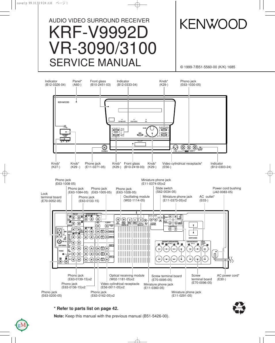
Indicator Panel From glass Indicator Knob Phono lack
(1312-0326-04) (A60-) 1310-2451413) (812-0333-04) (K29-) (E63-1030-05)
r
KENWOOD
I: :
I:| m1, 1;
3e W mean;-
2 505
P1122" m W w Om
I:| 7-
*C'O) : @ (C C OM13
rnauzs Ham 1 mlm.
Knob Knob Phonejack Knob Front glass Knob Video cylindrical receptacle Indicator
(K27-) (K29 -) (E11-0271-05) (K29-) (810-2418-03) (K29-) (E56-) (312-0303-24)
Phonojack Miniature phone jack
(1263-1 008-05) (E11-0374-05)x2
Phono jack Phono jack Phono jack Slide switch Power cord bushing
Lock (E63-1084-05) (E63-1005-05) (E63-1028-05) (862-0034-05) (J42-0083-05)
terminal board Phono jack Oscillating module Miniature phone lack AC outlet
(E70-0052-05) (E63-0133-15) (W02-7114-05I (EI1-0373-05IX2 (E03-I
@ @111 D
G D
DI G D 5.1m
momspznxans W
m u .msmfi 1:: m 1mm 5mm
; ( x < 1 m m r) O m
8W8 / V V \ / v I
< <1 m I
6W6) (DA/00 - g
v V K / If S
Phono jack Optical receiving module Screw terminal board Screw AC power cord
(E63-0139-15)x2 (W02-1181-05)x2 (570009505) terminal board (E30-)
Phono jack Video cylindrical receptacle Miniature phone jack (E70'0095-05)
(E63-0136-15)x2 (E56-0011-05)x2 (E1 1.035005)
Phono jack Phono lack Miniature phone jack
(E63-0200-05) (E63-0162-05)x2 (E1 1-0291-05)

* Refer to parts list on page 42.
Note: Keep this manual with the previous manual (851642600).

#

Page 2

coverlp 99.1030 9:24 AM Nb)?

we

KRF-V9992D/VR-3090/3100

CONTENTS / ACCESSORIES / CAUTIONS

Contents

CONTENTS / ACCESSORIES / CAUTIONS. ..... 2 EXPLODED VIEW ..... 41
ADJUSTMENT ............................................... .. 3 PARTS LIST .................. 42
PC BOARD .................... SPECIFICATIONS ..................................................... 44

SCHEMATIC DIAGRAM ...13

CAUTION: This manual is not available for informations, disassembly for repair, circuit description,
adjustment and wiring diagram. Please refer to KRF-V7771 D service manual(B51-5426-OO).
Also parts list is written a different part from B51-5426-00 manual.

COMPARISON TABLE
VR-2080 VR-3090 VR-2090 VFI-31OO KRF»V8881 D KRF-V9992D
X07 X07-2940-10 X07-2940-10 X07-2940-10 XO7-2940-10 X07-2940-21 X07-2940-21
X08 X08-2850-10 X08-2852-92 X08-2850-11 X08-2850-1 1 X08-2850-22 X08-2850-22
X11 X11-380040 X11-3803-81 X11-380041 X1 1-3802-91 X11-380021 X11-3800-71
X25 X25-60404 0 X25-6042-71 X25-604041 X25-6040-1 1 X25-604022 X25-604022

Accessories

r

Remote control unIt (1)
(A7071285705)

II

(Rch1oos) /
Battery coverlA0971130708)

BatterIes(R6/AA) (4)

FM indoor antenna (1)
(T9070841705)

Cautions

I " AM loop antenna (1) (T9070833705) .

Loop antenna stand (1)
(.11973645705)

AC plug adaptor (1)
: 02030115705)

' Use to adapt the plug on the power cord
to the shape of the wall outlet. (Accessory
only for reglons where use is necessary.)

How to reset the microcomputer

The microcomputer may malfunction (impossibility of operation,
erroneous display, etc.) when the power cord is unplugged and
plugged in again while the unit is in ON mode with the l/d) key
pressed or due to other external causes. In this case, execute the
procedure on the right to reset the microcomputer and return the
unit to the normal condition.

0 Resetting the mIcrocomputer clears the memory you entered and
returns it to the inItial condition when the unit left the factory.

U. SA. and Canada

0 Unplug the power cord from the wall outlet.
9 While holding the l/(l) (ON/STANDBY) key depressed, plug the
power cord into the wall outlet again.

Expect for USA. and Canada

0 With the power cord plugged in, turn the POWER key OFF.
9 Whill holding down the ON/STANDBY key, press POWER key.

, Memory backup function

Please note that the following items will be deleted trom
this units memory if the power cord is disconnected
from the AC outlet for approximately three days.

0 The input selection is cleared and the Tuner" input is selected.

0 The volume setting is cleared and the volume is set to -66 dB".

oThe receiving band setting is cleared and the FM" band is
selected.

I The frequency setting is cleared and 87.5 MHz is selected.
0 The preset statIon memory Is cleared.
o The surround setting Is cleared and reset to the lnlIlaI condition.