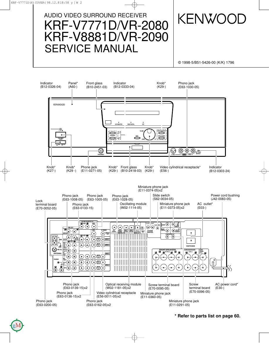
Kenwood VR 2080 Service Manual

This is the 62 pages manual for Kenwood VR 2080 Service Manual.
Read or download the pdf for free. If you want to contribute, please mail your pdfs to info@audioservicemanuals.com.

Page: 1 / 62
left right
Kenwood VR 2080 Service Manual

Extracted text from Kenwood VR 2080 Service Manual (Ocr-read)


Page 2

JKRF7V7771D(K)COVER(98t12t818:58 y [w 3
KRF-V7771DN8881D/VR-2080/2090

K

+

CONTENTS / ACCESSORIES / CAUTIONS

Contents
CONTENTS / ACCESSORIES / CAUTIONS.
CONTROLS ....................................................
DISASSEMBLY FOR REPAIR.
BLOCK DIAGRAM ...................
CIRCUIT DESCRIPTION.
ADJUSTMENT .................


Accessories
Check that the following accessories are present.

WIRING DIAGRAM.
PC BOARD ..........

SCHEMATIC DIAGRAM.
EXPLODED VIEW ..........
PARTS LIST .........
SPECIFICATIONS


Remote control unit (1) :" ' AM loop antenna (1) (TQOVOSSSVOS) """""" I AC plug adapter (1)
(A7071191705) I Loop antenna stand (1) (E0370115705)
(J1973645705)

(Rch0907)
Battery cover(A0970378708)

BatterieisG/AA) (4)

FM Indoor antenna (1)
(Tgorosssrom

I @fl

Use to adapt the plug on the power cord
to the shape of the wall outlet. (Accessory
only for regions where use Is necessary.)

Cautions
How to reset the microcomputer

The microcomputer may malfunction (impossibility at operation,
erroneous display, etc.) when the power cord is unplugged and
plugged in again while the unit is in ON mode with the I/d) key
pressed or due to other external causes. In this case, execute the
procedure on the right to reset the microcomputer and return the
unit to the normal condition.

0 Resetting the microcomputer clears the memow you entered and
returns it to the initial condition when the unIt left the factory.

USA. and Canada

0 Unplug the power cord from the wall outlet.
9 While holding the l/L') (ON/STANDBY) key depressed, plug the
power cord into the wall outlet again.

Expect for USA. and Canada

OWith the power cord plugged in, turn the POWER key OFF.
9 Whill holding down the ON/STANDBV key, press POWER key.

Memory backup function

Please note that the following items will be deleted from
this units memory if the power cord is disconnected
from the AC outlet for approximately three days.

0 The input selection is cleared and the Tuner" input Is selected.

0 The volume setting is cleared and the volume is set to -65 dB".

0 The receIVIng band setting is cleared and the FM band Is
selected.

o The frequency setting is cleared and 87.5 MHZ Is selected.
0 The preset station memory is cleared.
o The surround setting is cleared and reset to the initial condition.

Page 38

09

>14 New Parts
Parts Without Pans No. are not supphed.

%

>1: New Pans

Parts Without Parts No. are not supphed.

Les amcles non mentionnes dens 1e Parts No. ne son: pas fourms, 0 Les articles non menuonnes dens Is Parts N01 ne sont pas fourms. 9
Terle ohne Parts No. warden mcnt gehefen. TezIe ohne Parts No. werden mcm gehefen
- NM . . '- - Add- . . '- -
R21. No ff; MI Pans No. I Descnptmn I 2,113,, Rafi. R21. No ms m Pans Nu. Descrlptlon £553" "mks
KRF-V7771 D/V8881 D/VR-2080/2090 A; 623 1C 15302737475 AC POWER CORD K2P2
A 623 1C E30-2788-05 AC POWER CORD M1 M2
601 1A >14 A01-3525-11 METALLIC CABINET KP1Y1 A 623 1C E30-2789-05 AC POWER CORD Y1
601 1A >14 A01 >3525-11 METALLIC CABINET KZPZMZ A 623 1C E30-2867-05 AC POWER CORD C1 CZ
601 1A >14 A01 >3525-11 METALLIC CABINET M1 624 13,2C >14 E35»2056-05 FLAT CABLE 29P
601 1A >14 A01-3527-11 METALLIC CABINET C1 C2
602 1A A09»0378-08 BATTERV COVER 625 2A,1 C >14 E35-2057-05 FLAT CABLE 13P
608 2A >14 A60-1310-12 PANEL KZPZ 630 2A G11-0155-14 SOFT TAPE (40X9X2)
608 2A >14 A60-1311-22 PANEL M2 631 2A G11-0185-04 SOFTTAPE (120X5X2)
608 2A >14 A60-1312-22 PANEL C2 632 23 G11»2405-04 SOFT TAPE
608 2A >14 A60-1326-12 PANEL KP1
608 2A >14 A60-1327-22 PANEL M1 - >14 H10-7416-O2 POLYSTYRENE FOAMED FIXTURE
- >14 H10-7417-12 POLYSTYRENE FOAMED FIXTURE
608 2A >14 A60»1329-12 PANEL C1 - >14 H11-0094-04 POLYSTYRENE FOAMED BOARD
608 2A >14 A60-1400-12 PANEL Y1 - H25-0232-04 PROTECTION BAG (235X3SOX0.03)
609 1A >14 A70-1191-05 REMOTE CONTROLLER ASSY - H25-0661-04 PROTECTION BAG
612 2A >14 301 -0533-21 PANEL ESCUTCHEON K2P2M2 - >14 H50-2709-04 ITEM CARTON CASE KZPZ
612 2A >14 B01 >0533-21 PANEL ESCUTCHEON M1 - >1: H50-2711-04 ITEM CARTON CASE M2
612 2A >14 301 0534-21 PANEL ESCUTCHEON C1 - >14 H50-2712-04 ITEM CARTON CASE CZ
612 2A >14 301 -0534-21 PANEL ESCUTCHEON C1 CZ - >14 H50»2736-04 ITEM CARTON CASE KP1
612 2A >14 301 -0536-11 PANEL ESCUTCHEON KP1Y1 - >14 H50-2737-04 ITEM CARTON CASE Y1
613 2A >14 307-2396-12 ESCUTCHEON KP1Y1 - >14 H50-2738-04 ITEM CARTON CASE M1
613 2A >14 307-2396-12 ESCUTCHEON K2P2M2 - >14 H50»2739-04 ITEM CARTON CASE C1
613 2A >14 307-2396-12 ESCUTCHEON M1
613 2A >14 307-2397-12 ESCUTCHEON C1 C2 635 23,2C J02-1170-03 FOOT C1 C2
614 2A >14 310-2418-03 FRONT GLASS 635 23,2C J02-1404-13 FOOT (D:46,H=18 5,T) KP1Y1
635 23,2C >14 J02-1404-13 FOOT (D:46,H:18 5,T) K2P2M2
615 2A >14 310-2451-03 FRONT GLASS 635 23,2C J02-1404-13 FOOT D:46,H:18 5,T) M1
616 2B >14 312-0303-24 INDICATOR 637 13 J19-3300-05 UNIT HOLDER
617 2A >14 312-0326-04 INDICATOR
618 2A >14 312-0331-04 INDICATOR 638 1B J19-3324-15 UNIT HOLDER
619 2A >14 312-0333-04 INDICATOR A 639 1C J42-0083-O5 POWER CORD BUSHING
640 1A J19-3645-05 LOOP ANTENNA STAND
- 346-0197-00 QUESTIONNAIRE CARD KK2 - J61-0098-05 WIRE BAND
- 346-0326-03 WARRANTY CARD C1 C2
346-0330-03 WARRANTY CARD KKZY1 643 2A >14 K27-2248-04 KNOB (BUT-ION) M1 M2
- 346-0336-03 WARRANTY CARD P1 P2 643 2A >14 K27»2260-04 KNOB (BUT-ION) C1 CZ
- 358-0513-04 CAUTION CARD (PRESET220-240) Y1 644 2A >14 K29-6852-04 KNOB KP1Y1
644 2A >14 K29-6852-04 KNOB K2P2M2
358»0964-13 CAUTION CARD KK2Y1 644 2A >14 K29-6852-O4 KNOB
- 358-0966-13 CAUTION CARD M1 M2
- 358-0967-03 CAUTION CARD P1 P2 644 2A >14 K29-6853-04 KNOB C1 C2
- 358-1546-03 CAUTION CARD C1 CZ 645 2A >14 K29-6855-03 KNOB KP1Y1
359-1104-00 SERVICE DIRECTORY Y1 645 2A >14 K29-6855-03 KNOB K2P2M2
645 2A >14 K29»6855-03 KNOB M1
- >14 359-1200-00 SUB-INSTRUCTION MANUAL KP1Y1 645 2A >14 K29-6856-03 KNOB C1 C2
- >14 359-1200-00 SUB-INSTRUCTION MANUAL K2P2
>14 359-1401 -00 SUB-INSTRUCTION MANUAL M1 C1 646 2A >14 K29-6858-12 KNOB KP1Y1
>14 359-1401-00 SUB-INSTRUCTION MANUAL M2C2 646 2A >14 K29»6858-12 KNOB K2P2M2
>14 359-1404-03 CATALOG KP1 646 2A >14 K29-6858-12 KNOB M1
646 2A >14 K29-6859-12 KNOB C2
>14 359-1404-03 CATALOG K2P2
>14 359-1405-00 GUIDE BOOK KKZ I1 650 13 >14 L07-2463-15 POWER TRANSFORMER KP1
>14 360-3576-00 INSTRUCTION MANUAL(ENG) A 650 13 >14 L07-2463-15 POWER TRANSFORMER K2P2
>14 360-3579-00 INSTRUCTION MANUAL(FRN) P1 P2 A 650 13 >14 L07-2464-15 POWER TRANSFORMER MZ
>14 360-3581 -00 INSTRUCTION MANUAL(CHINA) C1 C2 A 650 13 >14 L07-2465-15 POWER TRANSFORMER CZ
A 650 13 >14 L07-2511-05 POWER TRANSFORMER Y1
>14 360-3755-00 INSTRUCTION MANUAL(SPANISH) M1 M2
>14 360-3756-00 INSTRUCTION MANUAL(TAIWANESE) M1 M2 /1\ 650 13 >14 L07-2513-15 POWER TRANSFORMER M1
/1\ 650 13 >14 L07-2514-05 POWER TRANSFORMER C1
A 622 1A E03»0115-05 AC PLUG ADAPTER M1M2
A 623 1C E30-2787-05 AC POWER CORD KP1 655 1A T90-0833-05 LOOP ANTENNA
656 1A T90-0835-05 LEAD WIRE ANTENNA
L:Scand1nawa K : USA P : Canada R:Mex1m C 2 ChIna I:Ma1aysla L : Scandinawa K : USA P: Canada I : Mexico C 2 Chma I : MaIaysIa
V: PXIFar East, HawaH) T: Europe E : Eurupe G : Germany V 2 Chma (Shanghai) V: PXIFar East, Hawan) T : Europe E: Eurupe G : Germany V 2 Chma (Shanghai)
V : AAFESIEuere) X: Austraha I] : Russta H : Korea M 2 Other Areas A: Indicates saIer ErmcaI Dumpunenls, V : AAFESlEumpeI X: Ausnaha I] : Russra H : Korea M 2 Orher Areas A; IndIEEIES salary ErmEaI components,

'0
>
:u
_|
(n
E
(n
_|

:U
I
<
\l
\l
-L
U
2
m
m
m
\
<
I
N
o
m
0
\
N
o
(.0
O

a
I
<
\r
\r
\y
H
U
5
n
3
an
m
w
H
N
w
H
00
m
m
K
s
as
N