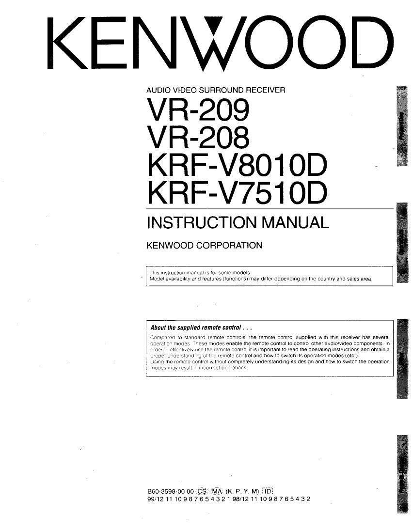
Kenwood VR 208 Owners Manual

This is the 24 pages manual for Kenwood VR 208 Owners Manual.
Read or download the pdf for free. If you want to contribute, please mail your pdfs to info@audioservicemanuals.com.

Page: 1 / 24
left right
Kenwood VR 208 Owners Manual

Extracted text from Kenwood VR 208 Owners Manual (Ocr-read)


Page 1

KENWOOD

AUDIO VIDEO SURROUND RECEIVER

VR-209

VR-208
KRF-V801 OD -
KRF-V751 OD

INSTRUCTION MANUAL

KENWOOD CORPORATION

Thls Instructlon manual ls tor some models
Model availaolllty and Ieatures (lunctlons) may dltler depending on the country and sales area

About the supplied remote control . . .

Compared to standard remote Controls, the remote control supolled wtth thus recelver has several
operation modes These modes enable the remote control to control other audIo/vrdeo components In
order In ettectwely use the remote control It IS Important to read the operating Instructlons and oblaln a
orcoe' 'moerstandlng ot the remote control and how to swuch lIS operatlon modes (etc)

Usrng the remote control wnhout completely understandtng llS deSIgn and how to Swttch the operation
mooes may result lll Incorrect operatlons

B60~3598-00 00 (:3 MA, (K, P, Y, M)

99/12111098765432198/12111098765432

Page 2

swag/applying thevgawer
Units are designed for operation as follows.

U.S.A. and Canada .
Australia ..............
China .........
Other countries .

.4 AC 120 V only
.. AC 240 V only
.............. AC 220 V only
AC 110-120 I 220-240 V switchable

' AC voltage selection

The AC voltage selector swnch on the (ear panel ls set to the voltage
that prevalls tn the area to whlch the unl! ls shlpoeo Belore
connectlng the power cord to your AC outlet make sure that the
setting poslllon ol thls swnch matches your llne voltage l' not l: nlus
be set to your voltage ln accordance Wlth the lOllowmg :llrectlon

AC voltage selector switch

Move swnch lever to g

matcnyournne are :25» .zmw :25-
._ _

voltage wtth a small
SCTerTIVeT or other
pomted tool

Note
Our warranty does not cover damage caused by excesslve llne
voltage due to lrnproper settlng ot the AC voltage selector sthch

flou:neadthis WWW enuresis" ' \
A , ) anngn

.Unpaelrina _

Unpack tne unlt carefully and nlake Sure 773' all accessones are ou
aSlde so they wlll not Be :05!

Examlne the u'llt for any posslplllty o snlcolna damage l" VCL. m
damaged o'tallstc operate notllyyouroeale rnmeolatel. tlt'cl '
was shleoeo I: you GITECII, not-r. lne S'llD' ng c mca .
delay Only the consonee (the peas 0' :ornoanv reaelv:
can llle a clalrn agalnst [he came snloplno oarnaoE
We recomlneno that you retaln the one a canon ano o Alng mater
rlals for use should you transport or snln tne u n tne More


Safetxkgficgcautians

WARNING :

TO PREVENT FIRE on ELECTRIC SHOCKT DO NOT
EXPOSE THIS APPLIANCE TO RAIN OR MOIS-
TURE.

AEGESSDFIES

FM lnooor antenna (ll

Loop antenna stand ll:
rm
\3/

Batterles (ROB/AAA) (A)

*AC plug adaptor (1T

Use to adapt the plug on the power
cord to the shape ol the wall outlet
(Accessory only for reglOllS where use
ls necessary.)

msx or ELECTRIC snocx
110 nor OPEN

a CAUTION

CAUTlON TO REDUCE THE RISK OF ELECTRIC SHOCK, DO NOT
REMOVE COVER (OR BACK) NO USER-SERVICEABLE PARTS
INSIDE, REFER SERVICING TO OUALlFlED SERVICE PERSONNEL

Cleaning

Do not use volatlle solvents such as alcohol palnt thlnnerl gasollne,
or oenzxne. etc to clean the cablnet Use a clean dry cloth

Do not use contact cleaners because lt could cause a malfunctlon
Be speclally carelul agalnst contact cleaners contalnlng OII for they
may deform the plastlc components

WITHIN AN EOUILATERAL TRIANGLE, IS INTENDED TO
ALERT THE USER TO THE PRESENCE OF UNINSULATED
DANGEROUS VOLTAGE WITHIN THE PRODUCTS EN-
CLOSURE THAT MAY BE OF SUFFICIENT MAGNITUDE
TO CONSTITUTE A RISK OF ELECTRIC SHOCK TO PER-
SONS.

@ THE LIGHTNING FLASH WITH ARROWHEAD SYMBOLv

THE EXCLAMATION POINT WITHIN AN EQUILATERAL TFllv
A ANGLE IS INTENDED TO ALERT THE USER TO THE FRESV
ENCE OF IMPORTANT OPERATING AND MAINTENANCE
(SERVICING) INSTRUCTIONS IN THE LITERATURE AC7

COMPANVING THE APPLlANCE

Page 8

Connecting video components ,

mm lem mm: m

ruvn n."- my.

OUT

DVD player or L0 player

- DVD player or LD player -J

VIDEO IN
a

VIdeo Inputs
(Yellow RCA DIn cord)

OUT OUT
TVideo deck
ou my . V OUT
h I: I 1
oo. 17 En
IN IN
Audio Inputs and outputs Vlden Inputs
(Red and thle RCA pIn cords) ans Outputs
1 1 77 (Yellow RCA
Dil'l cords)

Monitor TV

' A video component with digital audio outputs should be con-

nected to the VIDE02 or VlDE03 jacks.

Digital connections

The dIgIIal In lacks can acceDI elhe' Dolby DIgIIa 'AC SI 0' DCI,
sIgnals ConnectcomoonemsceuableGloulDunInGDolvaIgnaIIACr

a) or slannard PCM formal dlgllaI'SlQlalS


IE-:;igricee

faraw-
v, A uc \:
Io aooogoeoloDL ntx/g

gelcglecmoo IENSV


mummm.
Remove the

DiolecIIon cas
when usmg the
VlDEO 3 lack

mic: man:
. -_,_

or ODtICal
my
cable

OPTICAL DIGITAL OUT
(AUDlO)

Component with an Dolby Digital
(or PCM) OPTICAL DIGITAL OUT

Connect the wow SIgI , and analog
audIo SIgnals to the VIDEO 3 lacks
(See 'Connectlng Video compo-

OPTICAL COAXIAL .

DIGITAL DIGITAL ems

OUT GLIT COAXIAL DIGITAL OUT.
(AUDIO; (ADDIOI (AUDIO)

I 3 Component with an Dolby Digital

(07 FCM) COAXIAL DIGITAL OUT


RF digital demodulator
(DEM-9991 D)
(sold separately)

Connect the vudeo slgnal and analog
audlo SIgnals to the VIDEO 2 jacks
(See Connecnng VIdeO compor
DOLBV DIGITAL ems )
Fl: OUT

(AUDIOI


LD player

To COTVIEII an L0 D an? .\ I'l a DIGITAL RF OUT connect the LD Dlayer
0 'he KENWCOD RF (1 anal Demodulaim lDEMQgSlD)

N mnecl e DlGlT " OUTIacKs cl ire Oemoumatonome DIGITAL
lN lacks Oil erer

Connecl the yIueG slgnaI and analog am 0 SIgnaIs 13 {he VIDEO 2 or
VlDEC : lacks (See CUFHQCLIIQ VIneo componenls)

It you have connected any digital components to the receiver, be

sure to read the Input mode settings" section on the following
page carefully.

L I

.,