Kenwood UD 705 Service Manual

This is the 14 pages manual for Kenwood UD 705 Service Manual.
Read or download the pdf for free. If you want to contribute, please mail your pdfs to info@audioservicemanuals.com.

Page: 1 / 14
left right
Kenwood UD 705 Service Manual

Extracted text from Kenwood UD 705 Service Manual (Ocr-read)


Page 1

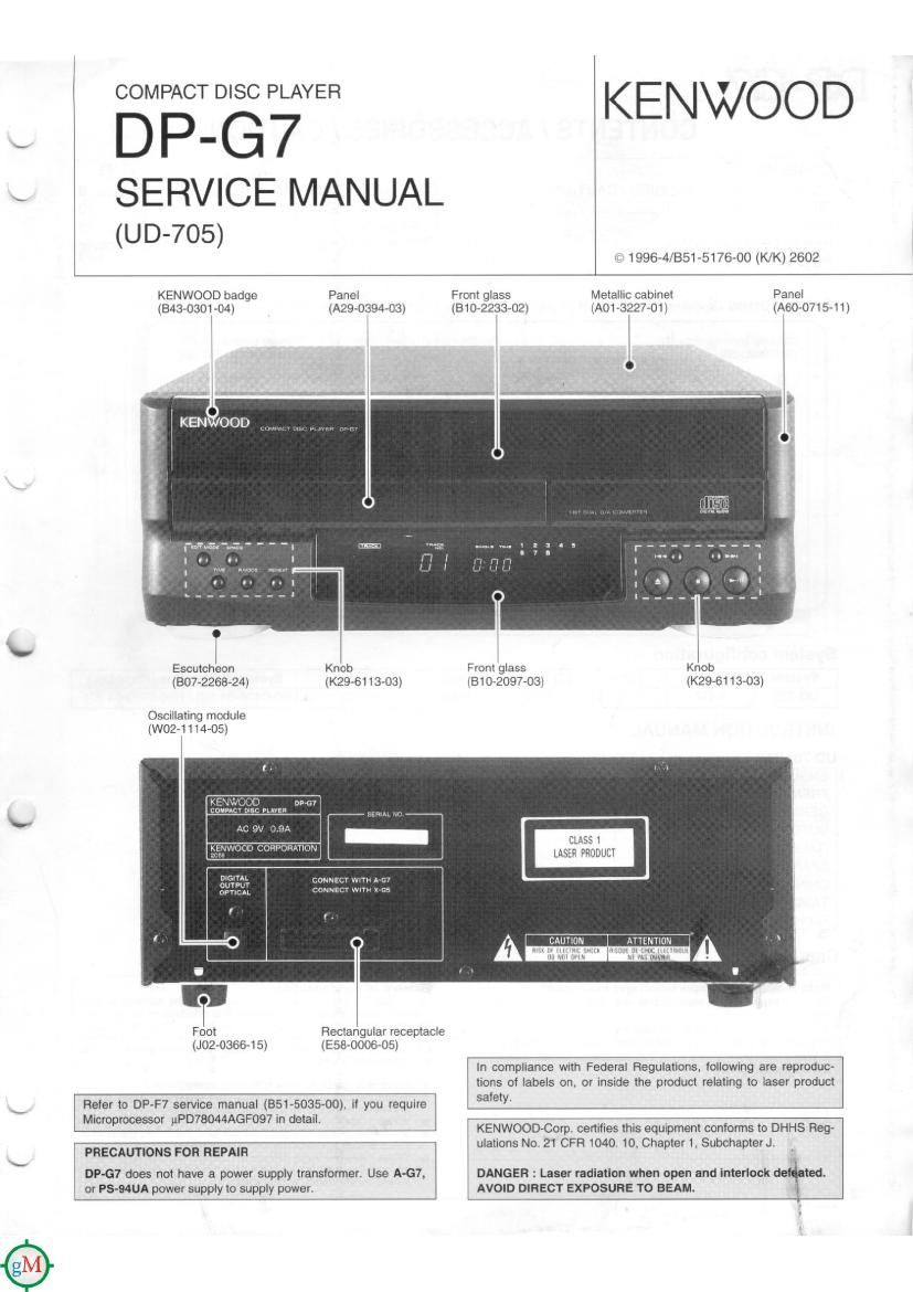
COMPACT DlSC PLAYER KE NWOO D
DP-G7

SERVICE MANUAL
(up-705)

is?» 1996-4/851-5176-00 (K/K) 2602

KENWOOD badge Panel Front glass Metallic cabinet Panel
(E43-0301-O4) (A29-0394-03) (310-2233-02) (A01 ~3227v01) (A60-O715-11)
l

Escutcheon Knob Front glass Knob
(307-2268-24) (K29-61 13-03) (81072097703) (K296113013)

Oscillating module
(W02-1114-05)

ummr
Oumr cowuacr wnu
OPTICAL CONNm wlm

l l .

Foot
(JOE-03664 5)

Rectangular receptacle
(Esa-oooa-os)

In compliance with Federal Regulations, iollowing are reproduc-
tions of labels on, or inside the product relating to laser product

Refer to DPF7 service manual (351-5035-00). if you require safe!-

Microprocessor uPD7BO44AGF097 In detaili

KENWOOD-Corp cenilies this equipment conforms to DHHS Reg-

. Ft 1 . 1 h t .
PRECAUTIONS FOFI REPAIR ulatrons No 21 CF 040 O. C ap er 1, Subchapter .1 .
DP-G7 does not have a power supply transformer. Use A-G7, DANGER : Laser radiation when open and interiock de ted.
or PS-MUA power supply to supply power. AVOID DIRECT EXPOSURE TO BEAM. 1

Page 2

DP-G7

ADJUSTMENT

i
INPUT SET- PLAYER ALIGNMENT
No. ITEM TINGS OUTPUT SETTINGS SETTINGS POINTS ALIGN FOR FIG.
On the power from
. . 0.06 to 015 mW
Eva'flfe55fl'1rg :3: (When the diffraction
Apply the sensor section AC ON. (Test mode] $3,223 fiiaogzcg:
1 LASER POWER - of optical power meter Press the DOWN - levgel of 1 0 V _ or (a)
on the pickup lens. key. then-confirm more and 1h: TE
that theoglnsplay '5 (servo open) level of
0.6 Vp-p or more. the
pickup is acceptable.)
. Set the unit to test
Connect an oscrlloscope
2 TRACKING ERROR Test disc as follows. diffieflfizéhgafik TE BALANCE scam/'32:? (c)
BALANCE Type 4 CH11RF (CN3 pin 1) k 4th 1. th VR2 pp 1 p
CH2:TE (CNS pin 6) a" .9" cm. "I .3 ms
the display IS 03 ,
Connect an oscilloscope Smegg: $2,125: :3
FOCUS ERROR Test disc as follows. ' FE BALANCE .
3 BALANCE Type 4 CH12RF (CNS pin 1) Raw/123w? I VR1 Opt'mur" eye Pane (d)
CH2:TE (CN3 pin 6) "m . .. 9.. 'Sp 3"
IS 05 .
Test disc ,
A [Type 4 I f cennserg f 2.: tr? CNS 5:22? 32:5: 11:? TRACKING T VTVM h Id
pp y srgna 0 pm - o w IC you _ we 5 5 cu
4 TRACKING GAIN 1.0 kHz, connect an oscilloscope 15m: aliektgfsn Izmis (Bi/2': read the same value. (e)
SDmVrms to or AC voltmeters. 05. p y
CNS pin 56. '
Note:

Type 4 disc: SONY YEDS-18 Test Disc or equivalent.
LPF: Around 47 kn+ 390 pF or so.
Step 1~4 are in Test Made.

(a) Laser power

Pickup

0,06 \ 0.15

Optical power meter

(e) Tracking gain

1.0 kHz
50 mVrms

CNS