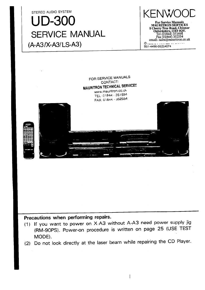
Kenwood UD 300 Service Manual

This is the 134 pages manual for Kenwood UD 300 Service Manual.
Read or download the pdf for free. If you want to contribute, please mail your pdfs to info@audioservicemanuals.com.

Page: 1 / 134
left right
Kenwood UD 300 Service Manual

Extracted text from Kenwood UD 300 Service Manual (Ocr-read)


Page 1

KENWOOE
U For Service Manuals
MAURITRON SERVICES

8 Chem Trey Road Chinnor
SERVICE MANUAL °¥2f8lé23°3§?593
Fax $018443 352554
cmallz- salcs@mauntron.co.uk

(AAS IX'ASI LSA3) . alabaoagslaaa " "

FOR SERVlCE MANUALS
CONTACT:
MAURITHON TECHNICAL SERVICES
www.mauritron.co.uk
TEL; 01844 - 351893

FAX: 01844 - 352554

Precautions when performing repairs.

(1) If you want to power on X4A3 without A-A3 need power supply jig
lRM-QOPS). Power-on procedure is written on page 25 (USE TEST
MODE).

(2) Do not look directly at the laser beam while repairing the CD Player.

Page 2

U D-3OO

CONTENTS

AMPLIFIER (A-A3)
DECK, CO, TUNER(X-A3).
CONTROL AND INDICATOR ......................................... 5
REMOTE CONTROL UNIT
SYSTEM CONNECTIONS.
DISASSEMaLY FOR REPAIR
BLOCK DIAGRAM
AMP SECTIONI.I...I.........I...I.u.
TUNER SECTION.
CD SECTION.....
DECK SECTION17
CIRCUIT DESCRIPTION .......
MECHANISM DESCRIPTION.
CD PLAYER ...................
CASSETTE DECK ........................................................ 50
ADJUSTMENT .................................................................... 58

ACCESSORIES

0 AM Iooo antenna .. I . FM Indoor amenna I

USO-1317405) (T900175-05)

- Remote zonIrOI un-I I - Bananas (Ros/AN 2

ha
an
II

(X944 0qu 1)
BATTERY COVER
(Ans-0126413)

L

can
an:
aaan
can
Dunn

I. 8 $2 INSTRUCTION MANUAL

EGO-075100 (ENGLISH) EGO-075500 (ITA) E
EGO-075200 (FIRE) RE
EGO-0753430 (GER) E
55041754430 (JAP) E

AMPLIFIER (A-AS)
WIRING DIAGRAM ..................................................... 59
PC BOARDI....,W......
SCHEMATIC DIAGRAM

CASSETTE DECK (X-A3)
WIRING DIAGRAM 51
PC BOARD ................ - ............................................... a 2
SCHEMATIC DIAGRAM

EXPLODED VIEW.
CD MECHANISM
CASSETTE MECHANlSM....,......I....,...............

-70
3

SPEAKER .........................................................


SPEC!FICATIONSI.............,_...I..I..m._...,_.............

. Amemu mum. I
(75 [1/300 III
(Encem In: some areas!

0 AC plug adapIOr I
(Except (or some areas)

\

(503-01 ISOSIM

(TBO-OIBS-OSITE

Arum: haldcr

(J 1 max 54m

BSD-0756430 (CHI) M
BEG-075700 (SPA) M,E
BED-0756430 (AHA) M

Page 51

U U'OUU
MECHANISM DESCRIPTION

STOP -e FWD FLAY/ REC (The head is in the forward -'
transport position when the drive stops.)

1 Press the keyJhe CPM starts running. 4 Since the entrance of the inner track of the cam gear
2 After about 300 ms, the solenoid is energized for 150 (324) passes when the solenoid is energized for 150 ms
ms, and the boss(A) oi the trigger arm (315) disengages the boss (A) of the shift lever selector (314) moves along
from the stop lever (B) of the play cam gear (314). the outer track. and the P shift lever (309) remains
Fig. 1 stationary.
Fig. 3
@m6 388 /388
3l5 /

3
324 . \

3l5

3l4
Fig. 1 Fig. 3
3 The head chassis assembly (301) is pushed down by the
spring (347) so the cam gear (324) rotates slightly, the 5 The shift lever is lifted by the cam of the play cam gear.
Fw (R) gear engages with the cam gear, and the gears and the head chassis assembly is raised.
start rotating. Fig. 4

Fig. 2

Fig.2 FOR SERVICE MANUALS Fig» 4
CONTACT:

MAURITRON TECHNICAL SERVICE?
www.mauritron.co.uk 51
TEL: 01844 . 351894
FAX: 01844 - 352554

Page 55

U LJ'OUU
MECHANlSM DESCRIPTIO

Assembly procedure
1 Install the brake arm and is spring the clutch arm spring,
and me shift lever seleclor . andils spring on the

mechanism chassis.
CLUTCN ARM SP

Fig. 1

C
2 Install the clutch assembly on the mechanism chassis. 3 Install the FR arm. FR gear. and HEW gear on the
Fig. 2 mechanism chassis.

Fig, 3

IIOM :01

é FOR SERVICE MANUALS

CO NTACT:
MAURITRON TECHNlCAL SERVICES

www.mauritron.co.uk
TEL 01844 A 351694
FAX: 01844 - 352554

55