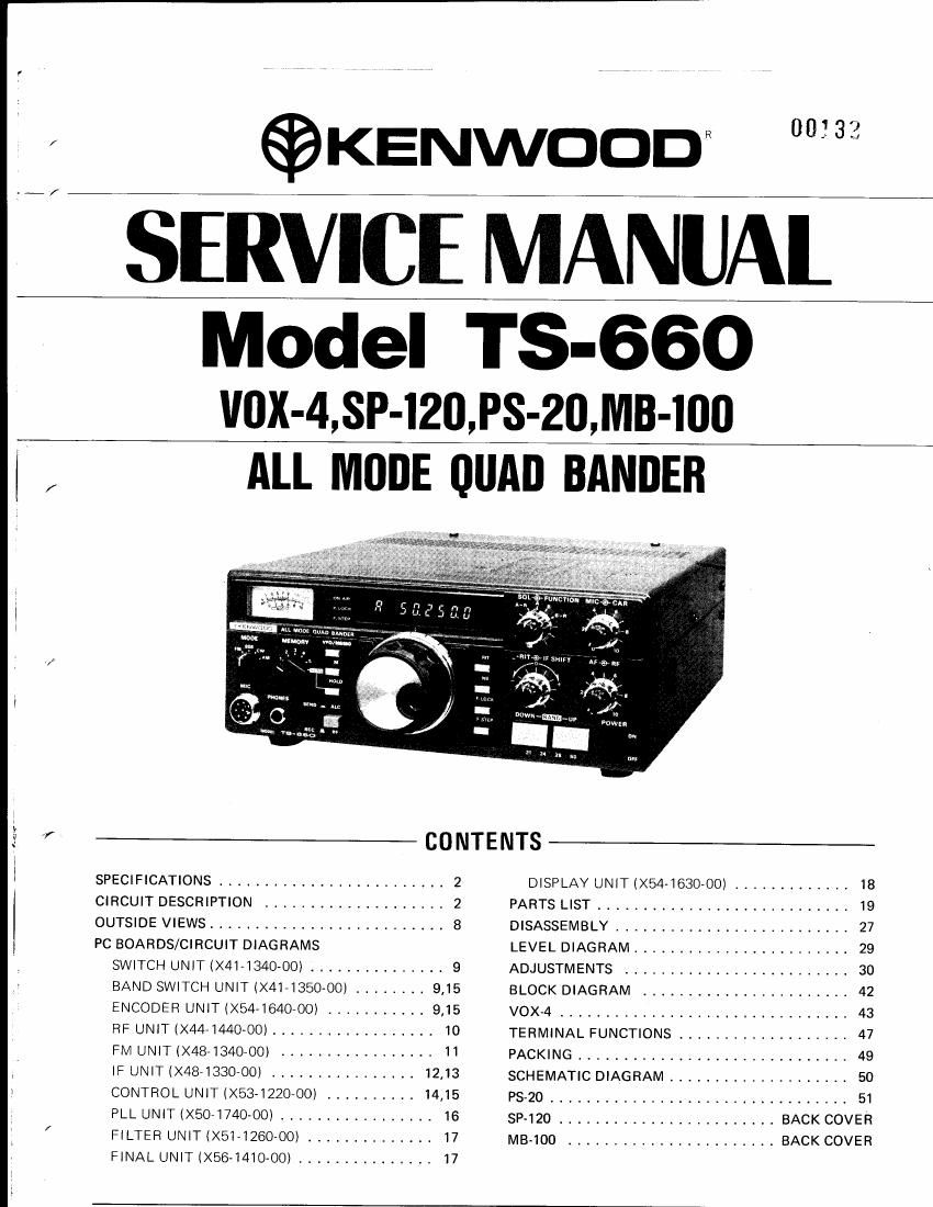
Kenwood TS 660 Service Manual

This is the 54 pages manual for Kenwood TS 660 Service Manual.
Read or download the pdf for free. If you want to contribute, please mail your pdfs to info@audioservicemanuals.com.

Page: 1 / 54
left right
Kenwood TS 660 Service Manual

Extracted text from Kenwood TS 660 Service Manual (Ocr-read)


Page 1

©KENWDODR 00333
/
k /
Madel I 5-660
VOX-4 SP-IZIJ PS-20 MB-IOO
! !
, ALL MODE QUAD BANDEB
I
I. ,
.:. r CONTENTS
I SPECIFICATIONS ......................... 2 DISPLAY UNIT (X54~1630-OO) ............. 18
CIRCUIT DESCRIPTION .................... 2 PARTS LIST ............................ 19
OUTSIDE VIEWS .......................... 8 DISASSEMBLY .......................... 27
I PC BOARDS/CIRCUIT DIAGRAMS LEVEL DIAGRAM ........................ 29
SWITCH UNIT BAND SWITCH UNIT IX41-1350~00) ........ 9,15 BLOCK DIAGRAM ...................... 42
ENCODER UNIT IX541640-OO) ........... 9,15 VOX-4 ................................ 43
RF UNIT IX44-I440'00) .................. IO TERMINAL FUNCTIONS ................... 47
FM UNIT (X484340-OOI ----------------- 11 PACKING .............................. 49
IF UNIT IX48-1330700I ................ 12.13 SCHEMATIC DIAGRAM .................... 50
CONTROL UNIT IX53-1220700) .......... 14,15 PS-20 ,,,,,,,,,,,,,,,,,,,,,,,,,,,,,,,,, 51
PLL UNIT (X507174O-OO) ................. 16 SP~120 ........................ BACK COVER
/ FILTER UNIT (XE-126000) .............. I7 MB-IOO ....................... BACK COVER
FINAL UNIT (X56-I4IO-OOI ............... 17

Page 2

SPECIFICATIONS/CIRCUIT DESCRIPTION

[GENERAL]

Frequency Range:

Mode:

Frequency Stability: (At room temperature)

Antenna lmpedance:
Power Requirements:

Semiconductor Complement:

Dimensions (profections excluded):
Weight:

[TRANSMITTER SECTION]
RF Output Power:

Carrier Suppression:
Sidebsnd Suppression:
Spurious Radiation:

Maximum Frequency Deviation (FM):
Microphone Impedance:

15 meter band 21,0000~ 21.4500 MHZ

12 meter band 24.5000\ 24.9999 MHZ (Receive only)

10 meter band 28.0000~ 29.7000 MHZ

6 meter band 50.0000~ 53.9000 MHz

FM (F3), SSE (Aaj), CW (All, AM (A3)

Within 1 200 Hz during the first hour after 1 minute of warmup
Within 1 30 Hz during any 30 minutes after warmup

50 I?

12~ 16 VDC (13.8 VDC nominali

Transmit (max) 4 A (SWR: Less than l.5l

Receive 1 A
ICs 35
FETs 22
Transistors 156
Diodes 2 1 7

Display tube 1
241 (971/2)Wx94i3-11/161Hx236 (9-5/16")D mm
4.9 kg (10.8 lbs)

553, CW, FM 10 W
AM 4 W
Better than 40 dB
Better than 50 dB

21 > 28 MHz band Better than 40 dB
50 MHz band Better than 60 dB
a: 5 kHz

500 Il~ 50 kfl

Audio Frequency Response:

[RECEIVER SECTION]

Squeloh Sensitivity (FM):
Audio Output: 1.5 W

government amateur authorization,

RECEIVER CIRCUIT

There are two antenna terminals on the TS-660 : one for
BOMHZ ANT 1 and one for 21-28MH2 ANT2. The
50 MHZ antenna terminal can be switched to operate
the full 21-50MHZ range by means of a rearpanel
changeover switch 82. When ANT 1 is used for All»BAND
operation, ANT 2 is automatically grounded,

The receiver system is single conversion with an IF of
8.830kHz_ The FM is dual conversion with a 2nd lF of
455kHz.

Audio Output Impedance: 8 ~ 16 $2

400~2600 Hz (-6 dB)

0.25 iv for 10 dB SW
1 ,tv (or 10 as S/N

1 [1V (or 30 dB SW

0.4 uv for 12 dB SINAD

Better than 60 dB
Better than 70 dB
SSE, CW, AM 2.4 kHz (-5 dB), 4.2 kHz (-60 dB}

15 kHz (76 dB), 32 kHz (760 dB)

VK-BSA 6 kHz ( <6 dBl, 11 kHz (760 dB)
YK788C 500 Hz (~6 dBl, 1.5 kHz (~60 dBi
VKVBBCN 270 Hz ( 76 dEli, 1.1 kHz (760 dB)

Sensitivity: 883, CW
AM
FM
Image Ratio:
IF Rejection:
Selectivity:
FM
Optional Filter
AM filter
CW filter

0.32 («V (at threshold)

Note: Circuit and ratings may change wlthout notlce due to developments in technology.

" Will transmit on the new 12 meter band. A lead wired for preventing accidental transmission before

At the RF stage, the 50 MHz and 21-28 MHz inputs are in-
dependent, but become common from the mixer stage. The
50 MHz antenna signal enters through the transmission LPF
(Filter unit, L7~9l and then to the VHF antenna coils.
For HF bands (21728 MHz), the signal enters the RF unit
HF antenna coils directly. Changeover between these trans-
mission and reception antenna paths is accomplished by
diode switches, However, relays are used for band change-
over, Input signals are stepped up by the RF unit antenna
coils; VHF L3, 4 and HF antenna coils (L941) and RF
amplified by VHF C21 SSK73, 0r HF 05 : 33K73.

\

Page 17

Pc BOARD VIEWS TS-660

V F I LTE R UN IT (X51-1260-00) Components side ViBW

Lno
spa . m
N
o

SMA %=_)= RL4

m
+ 8|
L)
X5l-l260-QO ,__. C43
_ L7 L6 Om:
Il~ 624
N b N
u lg .-
M
m 3 c
.J __ g RLI
L9 C23 OI i
:1 ~81 5; i
3
[0 --vi-_- '09 :
249 b 0}!
---------~ 33-0
RLZ
_ L L4 czo I 1
C33 ' 9| 9° I a I
2 L_.._._.__.J L. 0 =3 I a I
l l 9 -- I l I
:27 m I I I
i__._...._| _ __ a g
cm no _
«b y? «48% in lo
_.... r__._.______ _ _
l___.___.J _
L14 Ll Clo C3 L2 TCI
L-_-__-J __ Q --'-- --.---
LIS as u 2 V

< Attachment direction of L1 >

@ Short jumper
ll

l

V FINAL UNIT (X56-1410-00)

01,2:23C1815(YlD1~3:1N60 D5,9, 13, 14: 151555
D6,7,10,11:M|402 D12 : V068 D8: MISOI

< Disconnecting the coaxial cab|e >

Coaxial cable
< Attachment direction of 01,2 >

Egg

~74
/

Longrnosed pl Iers

Hold the crimped metal sleeve with
Pliers and pull up as shown.

Components side view Caution ' DO NOT pull on the cable,

(:24 8
R5 RI
n h n --
CE J [0 c E 30 c: R9 0 c E a N
u
_ CIS
\ I I \ I \ ,
\ T3 I \ T2 / \ Tl I
__ x I 3 \ I \ /
cl3 l - o I _ I x __
g 5 03 ls l --- u, : 0' l
_ I U / \ / \
[I \ I / \ / \\
RA \ \ _
R6 fl C6 R2 I0
01 T4 0 r a 8 o C E a I 6 _
- m N o I
o 9 'U 4. u c; +00 2 E '-
0. U E U
N
VR2 8',_ c 05 van a] >
N ..
cs , s I +00 5
04 E - 02
R10
D2 (5%? ____l=_4. D. :8
xseqmo-oo '3
. m7
TXB