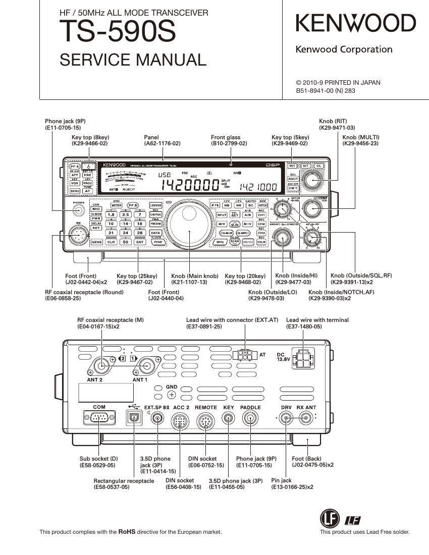
Kenwood TS 590 S Service Manual

This is the 162 pages manual for Kenwood TS 590 S Service Manual.
Read or download the pdf for free. If you want to contribute, please mail your pdfs to info@audioservicemanuals.com.

Page: 1 / 162
left right
Kenwood TS 590 S Service Manual

Extracted text from Kenwood TS 590 S Service Manual (Ocr-read)


Page 2

TS-SQOS

CONTENTS


DISASSEMBLY FOR REPAIR ................................................... 3
CIRCUIT DESCRIPTION ........
COMPONENTS DESCRIPTION .............................................. 20
SEMICONDUCTOR DATA ...................................................... 27
PARTS LIST ........... ..
EXPLODED VIEW ................................................................... 63
PACKING ................................................................................. 66
ADJUSTMENT ................ ..
TERMINAL FUNCTION .......................................................... 81
PC BOARD
FINAL UNIT (X45-391X-XX) .................. ..
CONTROL UNIT (X53-446X-XX) (A/3) .............................. 92
CONTROL UNIT (X53-446X-XX) (B,C/3) ........................... 96
DISPLAY UNIT (X54-3700-00) .. .
TX-RX UNIT (X57-785X-XX) ............................................
INTERCONNECTION DIAGRAM ......................................... 108
SCHEMATIC DIAGRAM .. .
BLOCK DIAGRAM ................................................................
LEVEL DIAGRAM ................................................................. 138
OPTIONAL ACCESSORIES
PS-60 (DC Power Supply) ................................................ 140
ARCP-590 (Radio Control Program) ............................... 140
ARHP-590 (Radio Host Program) .. .
ARUA-10 (USB Audio Controller) ................................... 140
SPECIFICATIONS ................................................................. 141
Document Copyrights Disclaimer
Copyright 2010 by Kenwood Corporation. All rights res While every precaution has been taken in the preparation
served. of this manual, Kenwood assumes no responsibility for era
No part of this manual may be reproduced, translated, rors or omissions. Neither is any liability assumed for dam»
distributed, or transmitted in any form or by any means, ages resulting from the use of the information contained
electronic, mechanical, photocopying, recording, or other- herein. Kenwood reserves the right to make changes to any
wise, for any purpose without the prior written permission products herein at any time for improvement purposes.

of Kenwood.

Page 31

TS-SQOS

SEMICONDUCTOR DATA

Pin No. Port Name IIO Function Pin No. Port Name IIO Function
129 VSS » GND 138 Al18l 0 Address bus for flash memory
130 A[13l 0 Address bus for flash memory 139 BCKXORT | Bit clock reception
131 A[14] 0 Address bus for flash memory 140 VSS » GND
132 CVDD | Core power supply (1.2V) 141 FSXORT l Frame synchronous reception
133 VSS » GND 142 BCKXORT O BrtflockéraDjzmrssrontfor A/D con-
134 A[15] 0 Address bus for flash memory ve 9' 3" COW 9'
135 A[16] 0 Address bus for flash memory 143 MCLKR 0 Master clock for A/D converter
Frame synchronous transmisslon for
136 DVDD | |/O power supply (3.3V) 144 FSXORT O AID converter and D/A converter
137 A[17l 0 Address bus for flash memory
Extended IIO Port
I Final unit (X45-391 A/2)
Pin No.) Pin name) Port name Function Activelevel Condition
IC1: TC74HC4094AFF (Shift register) Enable: FEN1
4 O1 2L 1.8M LPF relay H 1.705 g f < 2.50 (MHZ)
5 OZ 7L 7M LPF relay H 5.50 § f < 7.50 (MHZ)
6 Q3 14L 14M LPF relay H 10.5 § f < 14.50 (MHZ)
7 O4 3L 3.5M LPF relay H 2.50 g f < 4.00 (MHZ)
14 O5 28L Z4M/28M LPF relay H 21.50 é f < 30.0 (MHZ)
13 06 10L 10M LPF relay H 7.50 § f < 10.50 (MHZ)
12 Q7 21L 18M/21M LPF relay H 14.50§f<21.50 (MHZ)
11 ()8 5L 5M LPF relay H 4.00 § f < 5.50 (MHZ)
IC7: TC74HC4094AFF (Shift register) Enable: FEN1
4 O1 ATS In/Through switchlng relay H L: Through, H: In
5 OZ ANTZ HF ANTZ sztchlng relay L L: ANT1, H: ANT2
6 03 NC
7 Q4 50L 50M LPF relay H 49.0 § f < 54.0 (MHZ)
14 Q5 FANL Low speed/High speed H When the FANrotates, at either low or high speed,
It becomes actrve.
13 06 FANH High speed H When the FAN rotates at high speed, it becomes actrve.
12 07 NC
11 08 L (1) 50M coil H 49.0 § f < 54.0 (MHZ)
IC8: TC74HC4094AFF (Shift register) Enable: FEN2
. . . Phase difference correction C1
4 01 Cl (1) 2.5p capacitor swrtchlng H On: Active, Off: Inactlve
. . . Phase difference correction C2
5 02 Cl (2) 5p capacitor swrtchlng H On: Active, Off: Inactlve
. . . Phase difference correction C3
6 03 Cl (3) 10p capacitor sw1tchlng H On: Active, Off: Inactlve
. . . Phase difference correction C4
7 04 Cl (4) 18p capacrtor swrtchrng H On: Active, Off: lnactrve
. . . Phase difference correction C5
14 05 Cl (5) 399 capacrtor sztchlng H On: Active, Off: lnactrve
. . . Phase difference correction C6
13 06 Cl (6) 75p capacitor sztchlng H On: Active, Off: Inactlve

31

Page 71

Receiver Section

ADJUSTMENT

TS-SQOS

Measurement Adjustment
Item Condition Test- _ _ _ Specifications I Remarks
. Unit Terminal Unit Parts Method
equipment
0 Perform the following in the adjustment mode. Item 4 and 8~22.
To terminate the adjustment menu in the middle, save your settings with Menu No.60.
1. Trap 1) Display f.: 15.501 MHZ Tracking Rear ANT 1 TX-RX TC1OZ Adjust TC102 to
frequency Mode: USB generator panel lA/Zl get a null point
(E type only) PRE-AMP: ON at 15.501MHZ as
Spectrum TX-RX CN201 shown. 15.501MH2
0 15.5MHz analyzer (A/Z)
011.7MHZ 21 Display f.: 11.700MHZ TC101 Adjust TC101 to
Mode: USB get a null point at
PRE-AMP: ON 11.7MHz as shown.
Repeat the trap HJMHZ
frequency adjust»
ment 2 to 3 times,
alternating between
15.5MHZ and
11.7MHz.
2. HF BPF 11 Display f.: 7.200MHZ L133 Adjust the coils to
Mode: USB L150 obtain the frequency
PRE-AMP: ON L167 response as shown. 72K
21 Display f.: 14.200MHZ L134 K type
Mode: USB L153
PRE-AMP: ON L168 W
E type
W
3. IF Trap 1) Display f.: SOMHZ L135 Adjust L135 at
(73.095MHZ) Mode: USB 73.095MHZ to mini-
PRE»AMP: ON mum level.

73.095MHZ

71

Page 151

D

I E

P I Q

10

11

12

13

14

A | B | c |
TS-5908 Pc B0

ARD

DISPLAY UNIT (X54-3700-00) (A/GI: DISPLAY

Component side view (J79-0280-09 A/6)

|
PC BOARD

DISPLAY UNIT (X54-3700-00I IA/GI: DISPLAY
Component side view (J79-0280-09 A/6)

| R | s
TS-SQOS

mm

sue
1m

AGE/T

MIC

5111 I

I S113

5125 s12:
CW/FSK

I

| | | 5° I Iml
it;
Componentside 57 I I 51319 I 51511 I I 3:1; I
Layer1
Layer2 7
La erg S|I7 SIN SIZI SIN 5115
La:er4 I GENE I CLH I I II I ENT I I FINE
Foil side
DISPLAY UNIT
IX54-3700-00I IB/GI: MULCH/CH
® u
3/6 D
DISPLAY UNIT
IX54-3700-00I IE/6I: MIC
JEEU ® g g
I 2 1 w 51 3 ; 34 >
I 5 E 7 . é $1495 E C/G
5 DISPLAY UNIT

(X54-3700-00I IC/6I

: HI/LO (SHIFT/WIDTH), NOTCH/SOL

Sm
CL

uw MN MW cuz
J79-0280-09 N6 /
Ref. No. Address Ref. No. Address Ref. No. Address Ref. No. Address
I III: I I 55334 I I 5311 I I 13? I 0106 SH D135 3J D163 4D D191 3K
D101 3C D136 3J D164 3D D192 3K
D102 3D D137 4J D165 3E D193 4K
D103 4C D138 3K D166 4D D194 3L
D104 3D D139 3K D167 3E D195 3L
DISPLAY UNIT D105 3D D140 4K D168 3E D196 4L
D106 40 D141 3K D169 4E D197 3L
IX54'3700'00I ID/GI' AF/RF D107 35 D142 3L D170 3F D198 3M
D108 3E D143 4K D171 3F D199 4L
D109 4E D144 3L D172 4F D200 3M
D110 3F D145 3L D173 3F D201 3M
D111 3F D146 4L D174 36 D202 4M
D112 4F D147 3M D175 4F D203 3N
D113 3F D148 3M D176 36 D204 3N
D114 36 D149 4M D177 3H D205 4N
D115 4F D150 3N D178 46 D206 3N
D123 36 D151 3N D179 3H D207 30
FIG D124 36 D152 4N D180 3H D208 4N
I] D125 46 D153 3N D181 4H D209 30
g D126 3H D154 30 D182 3| D210 3P
1 m I] I] I] [l D127 3H D155 4N D183 3| D211 40
g ma D128 4H D156 30 D184 4| D212 3P
1:: u n n n 31:: :1 31:; :3 31:: :3 3:1: 2:
D131 4H D159 3P D187 4| D215 5H
D|SPLAY UN|T D132 31 D160 3P D188 3J D216 4P
(X54-3700-00) (F/6). PHONE D133 3J D161 3D D189 3J D217 3C
D134 4| D162 3D D190 4J D961 10B

10

11

12

13

14