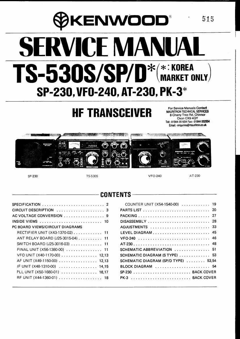
Kenwood TS 530 D Service Manual

This is the 59 pages manual for Kenwood TS 530 D Service Manual.
Read or download the pdf for free. If you want to contribute, please mail your pdfs to info@audioservicemanuals.com.

Page: 1 / 59
left right
Kenwood TS 530 D Service Manual

Extracted text from Kenwood TS 530 D Service Manual (Ocr-read)


Page 1

$KENWDDD ' 515

SERVICE MANUAL

TS-53OS/SP/D* 121132?qu

SP-230, VFO-240, [IT-230, PK-3*

HF TRANSCEIVER

For Service ManuaIs Contact
MAURITRON TECHNICAL SERVICES
8 Cherry Tree Rd, Chinnor
Oxon OX9 40!

Tel:- 01544-351694 Fax:- ()1va
Emaila enmities©craurilromom

SP-230 TS-SBOS VFD-240 AT~230
CO NTE NTS
SPECIFICATION .......................... 2 COUNTER UNIT (X54-1540-OO) ............ 19
CIRCUIT DESCRIPTION .................... 3 PARTS LIST ............................ 20
AC VOLTAGE CONVERSION ................. 9 PACKING .............................. 27
INSIDE VIEWS .......................... 10 DISASSEMBLY .......................... 28
PC BOARD VIEWS/CIRCUIT DIAGRAMS ADJUSTMENTS ......................... 33
RECTIFIER UNlT IX431370-02) ............ 11 LEVEL DIAGRAM ........................ 45
ANT RELAY BOARD (J253015~04) .......... 11 VFO<24O .............................. 46
SWITCH BOARD (J25-3016-O3) ............. 11 AT<230 ................................ 48
FINAL UNIT (X56-1380-00I ............... 11 SCHEMATIC ABBREVIATION ............... 51
VFO UNIT (X40-1170-00) ............... 12,13 SCHEMATIC DIAGRAM (8 TYPE) ............. 53
AF UNIT (X49-1150-00) ................ 12,13 SCHEMATIC DIAGRAM (SP/D TYPE) ........ 53,54
IF UNIT (WIS-131000) ................ 14,15 BLOCK DIAGRAM ....................... 54
PLL UNIT (X50~1680~01) ............... 16,17 SP-230 ........................ BACK COVER
RF UNIT (X44-1360~01) .................. 18 PK-3 ......................... BACK COVER

Page 2

firs-530$

SPECIFICATIONS

[GENERAL]

Frequency Range.

160 m Band 1.8 ~ 2.0 MHz
80 m Band 35 ~ 4.0 MHz
40 m Band 7.0 ~ 7.3 MHz
30 m Band 101 ~ 10.15 MHz
(10.0 MHz WWV)
20 m Band 14.0 ~ 14.35 MHz
17 m Band 18.068 ~ 18.168 MHz
15 m Band21.0 ~ 21.45 MHz
* 12 m Band 24.89 ~ 24.99 MHz
10 m Band 280 ~ 29.7 MHZ
SSE/CW
Within 1 kHz during the first hour after 1 minute of warmup.
Within 100 Hz during any 30 minute period thereafter.
1 10VAC/120VAC/24OVAC, 50/60 Hz
Transmit: 295 watts
Receive: 27 watts (with heaters off)
333 (13.3) x 133 (5.3) x 333 (13.3) mm(inch)

Modes ....................
Frequency Stability ..

Power Requirement....
Power Consumption

Dimensions.

Weight......... 12.8 kg (28.2 lbs)

[TRANSMITTER] TS-53OS/SP TS-SSOD
" Final Power Input .................................... 220W PEP for $53 operation 160W PEP for SSE operation
180W DC for CW operation 130W DC for CW operation

Audio Input impedance .. 500!) ~ 50 k9

RF Output Impedance. 50.0 ~ 7552

Carrier Suppression . Better than 40 dB

Sideband Suppression Better than 50 dB

Spurious Radiation ...... Better than 60 dB

Harmonic Radiation Better than 40 dB

Audio Freq. Response. 400 to 2,600 Hz, within «6 dB

ALC Input -10V DC Max

- For Service Manuals Contact

Linear Amp Relay Contact Ratlng 100V DC 1 A MAgRlTHON TECHNICAL SER

[RECEIVER] °"%"!£Ei§2§¢'"°

lel:- 01844351694 Fax:- 01844352554

Receiver Sensitivity . Email:- enmirles®mauritromoom

0.25 #Vat 10dBS+N/N

Image Ratio. Better than 60 dB
IF Rejection .. Better than 70 dB
Receiver Selectivity
SSE/CW ................................................ 2.4 kHz (-6 dB), 4.2 kHz (-60 dB)
CW Optional Filter
YK-88C 500 Hz (-6 dB), 1 .5 kHz (-60 d8)
YK<88CN 270 Hz (-6 dB), 1.1 kHz (-60 dB)
SSB Optional Filter
YK-BBSN 1.8 kHz (-6 dB). 33 kHz (-60 dB)
Notch-filter Attenuation Better than 20 dB(1.5 kHz)
Audio Output Impedance .. 8 ~ 169
Audio Output ................... 1.5W (8.0)
NOTE: The circuit and ratings may be changed without notice due to developments in
technology.

NOTE: For the TS-53OSP shipped to the USA, and for the TS»5300.

" Will transmit on the 17 and 12 meter bands,
Diodes installed for preventing accidental transmission before government Amateur
authorization.

Page 20

TS-5303

Not-l:
K USA,

Note 2:

T: Brltain W,

Europe X Australia

PARTS LIST

3. Resistance value

'-

®® CD -~ means 22 x101 = 2200110 2 kn)

Only special type 01 resistors (example

cement, metal lllm, etc) and

capacitors (example: electrolytic, tantalum. mylar, temp, coefl, capacnors) Example 221 a 22011 223 -. 22 It!) 225 -. 2 2 Mn
are detailed in the PARTS LIST, For the value 01 all common type corn- 222 -- 2 2 k!) 224 a 220 kfl
ponents, reler to the schematic diagram of the P.C board lllusllallofl
Resustors not otherwtse detailed are carbon type (1/4W or 1/8W) 4 T
Order carbon resaswrs and capacrtors according to the lollowlng example: ' J °°f""
= = +
A carbon res-star's part number is RDNBY 2E222J _5%lGold) K 10%(S'lve')
A ceramic capac-tor's number l5 CK45F1H1032. CC4STH1H220J, CAPACITORS
RESISTOR Type I Type II
1- Tvve of m. carbon resiswr CC .45 1H. IH 220 J ,cr :1? F, 11'! 103 ,.Z..
RD14BY RDMCY 1' Z 3 4 5 6 1 2 3 4 5 6
-(__;:>- 801488 (small sue) RDMCB (small snze) 1 = Type , ceramic, elecrrolyuc. etc. 4 = Voltage rating
2 = Shape _, round. square. etc 5 = Value
2' Wattage 3 = Temp range 5 = Tolerance
1W -- 3A 3W -v 3F 5W -. 3H 3' = Temp CoellICIent
2W » SD 4W a 3G
3 = C1345 O O a
Ceramic Capacrtor (type l) temperature coell capacutor 1 3' E CC45TH = 470 :60 ppm/ C
lst word C L P R S T U 2nd Word H J K L
(Color) (Black) (Red) Orange) (Yellow) (Green) (Blue) (Violet) ppm/ac $30 :60 :120 $250 2500
ppm/C O -80 -150 ~220 -330 _-470 -750
5 = Capacitor volue
2 ems 0 l H) 3 Examp'e 01° '" F
eramlc capact or type 100 V. 10 pF
Cord B D E F 101 - 100 pF
Operating temperature -30 -30 -30 -10 102 -o 100011)F = 00011:
°C +85 +85 +85 +70 10390.01uF
6 = Tolerance
Cord C D G J K M X Z P Nocurd
+40 +80 +100 Morethan10uF-10~ +50
(96) :025 '5 *2 *5 3 32° -20 -20 -0 Less than 4.7,.F A10~ + 75
Lou then 10 pF C015
(2)015
Cord a c n F G C°'°
(9F) $0.1 $0.25 20.5 :1 t2 '
l
Abbreviation Abbreviation 1
Cap Capacitor ML Mylar «Type I Type ll
C Ceramic S Styren
E Electrolytic T Tantalum
MC Mica
T3530 SEMICONDUCTOR it: New parts
Item Name Pam No. "1':ka Item Name Parts No. mgfis
Diode 1N60 V11-0051-05 Vari-cap 18V53A V11-4161-36
diode ISV54GC V11-4173-46 fl
181007 V11-4160-66
131555 v11-0076-05 LED 5'3 V11-6172-76
151587 V11-O370-OS ~
152588 V11-0414~05 205 V1 13162'96
Zener diode WZ-061 v11.0243-05
V03C V11«0290-05 200V 13A wz-oeo V11~0240-05
V063 V11-0219~05 100V 1t1A WZ-110 V11-4161-46
VOGE V11-0285-05 400V 1,1 A
VDBJ V11-0282-05 eoov 111A xz-055 v11.41os.5o
XZ-060 V11«4101-20
Varistor MV-13 V21-OOO4-05 XZ-OQO V11-4167-06
MV-203 Surge
absorber ERZDO3DK331
20
For Service Manuals Contact
IMURITRON TECHNICAL SERVICES
8 Cherry Tree Rd. Chmnor
Oxon OX9 4QY

14901844351894 Fax: 01844-35554
Emailz- enmllrlss@mauritrortmnt