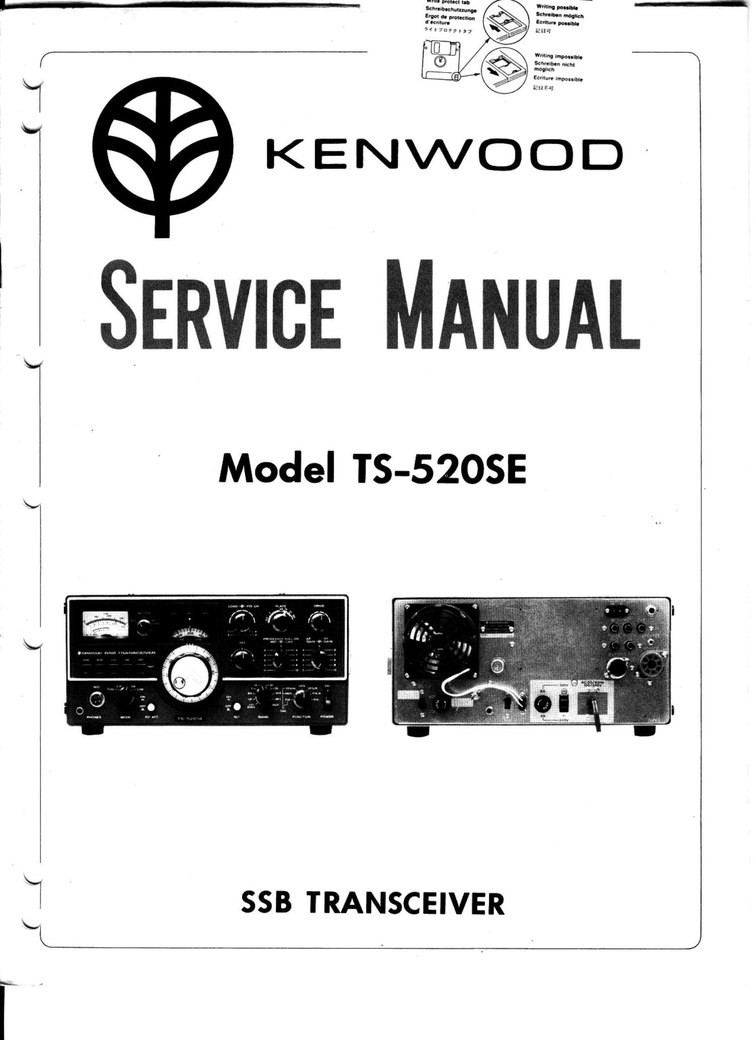
Kenwood TS 520 SE Service Manual

This is the 11 pages manual for Kenwood TS 520 SE Service Manual.
Read or download the pdf for free. If you want to contribute, please mail your pdfs to info@audioservicemanuals.com.

Page: 1 / 11
left right
Kenwood TS 520 SE Service Manual

Extracted text from Kenwood TS 520 SE Service Manual (Ocr-read)


Page 2

NOTICE

The differences from former 5205 are as follows.

1 Modifications for the elimination of the DC power function
1) The power transformer has been changed. {Windings for the converter have been eliminated)
2) The 12P concent plug has been eliminated.
3) The 10P terminal board and its bracket have been eliminated. (For DCDC converter.)

2. Modilication for the elimination of the X verter function
1} The 12P connector has been eliminated. [For X-verterl
2) The slide swnch and stopper have been eliminated.
3) Two 1P jacks have been eliminated. lX-verter, IN/OUT)
4) The rear panel has been modified. (This modification IS related to item 1.]

3. FIXCHAVR unit modifications to eliminate the DCDC converter [-6V}.
1) The oscHIation transformer has been eliminated.
2) The oscrllation transistor. Capacitor and Beetstor have been eliminated.
3) A connecting wire kit and solid resistor have been newly added.

4. The marker unit has been redesigned to New Circun
5. Modifications for the new introduction of the CW NARROW/WIDE switching lunction include

1) The switch name plate
2) The connecting wire kit to suit wiringmodifications
3} The paddle swnch

SPECIFICATIONS

GENERAL TRANSMITTER
Frequency Range: RF Input Power:
160 meter band - 1.80 to 2.00 MHz 120/220 VAC. or 220/240 VAC
80 meter band - 3.50 to 4.00 MHz 50/60 Hz operation I
40 meter band - 7.00 to 7.30 MHZ 200 watts PEP for $38 operation
20 meter band - 14.00 to 14.35 MHZ '50W3119 03 fO' CWooeration J

15 meter band - 21.00 to 21.45 MHz
10 meter band - 28.00 to 28.50 MHz (A)
- 28.50 to 29.10 MHz (B)
- 29.10 0 29.70 MHz 1C)
WWV -- 15.0 MHz (receive only)
Mode: SSB llUSB. LSB) or CW
Antenna Impedance: 50 ~ 75 ohms

Frequency Stability:

Carrier Suppression: Better then 40 db

Side Bend Suppression: (Better than 50 db

Spurious Radiation: Better than 40 dB,

Audio Input Sensitivity: - 60 db ( - 50 db maximum]
AF Response: 400 to 2.600 H2, within - 6db

RECEIVER

Within 100 Hz during any 30 minute period after warm-

up
Within 21:1 kHz during the first hour after 1 minute of
warm-up

Tubes and Semiconductors:

Tubes........,...... 3
Transistors ........ 49
FETS 19
Diodes.............. 95

Power Requirements:

120E220 VAC. or 220E240 VAC T
50/60 Hz operation

Receive .. 45 watts

Transmit l 280 watts [maximum]

Dimensions:
333 (13-1/8 Wide x 153 (6.0) high x 335 {13-3/16)
deep

Weight: 16 kg13521bs)

Sensitivity:
0.25 uV S+/N10 db or more
Selectivity:

$88 -2.4 kHzi-Gdb}
-4.2 kHzl-GO db]
CW# -O.5kHZi-6dbl

-1 5 kHzt-BOdb)
# (With optional CW filter installed)

Image Ratio: Better than 50 db
IF Rejection: Better than 50 db

AF Output Power:
1 Watt {8 ohms load, With less than 10% distortion)

AF Output Impedance: 4 to 16 ohms

(