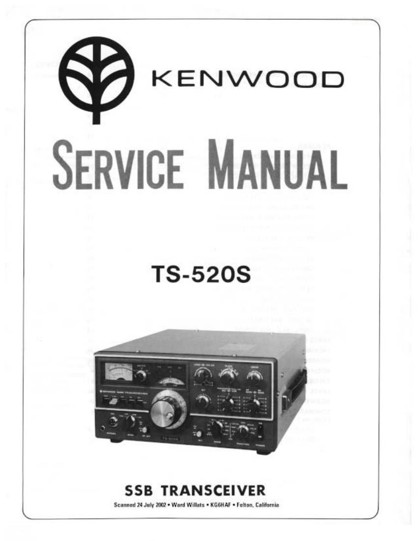
Kenwood TS 520 S Service Manual

This is the 57 pages manual for Kenwood TS 520 S Service Manual.
Read or download the pdf for free. If you want to contribute, please mail your pdfs to info@audioservicemanuals.com.

Page: 1 / 57
left right
Kenwood TS 520 S Service Manual

Extracted text from Kenwood TS 520 S Service Manual (Ocr-read)


Page 2

[3-5203 '

CONTENTS
SPECIFICATIONS ............................................. 3
TS-520 SERIES COMPARATIVE TABLE ......................... . . . 4
BLOCK DIAGRAM ........................................... 5
GENERAL ................................................. 6
CIRCUIT DESCRIPTION ....................................... 6
FUNCTIONAL DESCRIPTION .................................... 9
EXTERNAL VIEW ............................................. 12
PARTS ALIGNMENT ................ . ......................... 13
PC BOARD
VFO UNIT (X40-IO70-01) .................................... 14
RECTIFIER UNIT (X43-1090-02) ............................. 14
FIX CH, AVR UNIT (X43-1100~00) ............................ 15
HV UNIT (X43-1110-00) ................................... 15
OSC COIL UNIT (X44«1160-00) ............................... 16
ANT COIL UNIT (X44-1070»00) .............................. 16
MIXER COIL UNIT (X44-1080-00) ............................. 17
DRIVE COIL UNIT (X444090-00) ............................. 17
RF UNIT IX44-1200-00) .................................... 18
IF UNIT IX48-1060-01) .................................... 19
AF UNIT (X49-0008v01) ................................... 20
CARRIER UNIT IX50-0009-01) ............................... 21
MARKER UNIT IX52»0005-01) ............................... 21v
GENERATOR UNIT IX52-1090-00) ............................ 22
INDICATOR UNIT IX54-1280>00I ............................. 22
VOX UNIT (X54-0001700) .................................. 23
NB UNIT (X54-1080-10) .................................... 23
FINAL UNIT (X56-1220-00) ................ 24
PARTS LIST ................................................ 25
PACKING .................................................. 34
DISASSEMBLY .............................................. 35
MODIFICATION .................. .......................... 40
TROUBLESHOOTING ...... 41
LEVEL DIAGRAM ........................................... 44
ADJUSTMENTS ............................................. 45
SCHEMATIC DIAGRAM ........................................ 51
I OPTION I
DK~520 (For DG-S) ........................................ 4
DS-1A (DC-DC CONVERTER) ..................... . .......... 52

Page 10

15-5203

CIRCUIT DESCRIPTION/FUNCTIONAL DESCRIPTION

10. FIX CH, AVR Unit (X43-1100-00)

This unit includes a fixed channel crystal oscillator circuit,
9V AVR circuit and ~6V DC»DC converter circuit. The
crystal oscillator circuit 01 (ZSC4GOB) is a Pierce C-B circuit
and its output is obtained from the Darlington buffer con-
sisting of 02 and 03 (28C4GOB). TCI-TC4 trimmers are
provided for fine adjustment.

The 9V AVR circuit supplies power to the main oscillator
and control circuits. Q4 l2SA606L) is a current regulator,
05 and 06 (28C372) error voltage amplifiers, and O7 (280
372) is a temperature compensating transistor. D3 lWZOBl)
is the zener reference diode

An oscillator circuit is formed by 08 (28C735Y) and T1
operating at approximately 400 Hz, which is rectified by
D4»D7 (181555 X 4). A stabilized -6V source is obtained
through zener diode D8 (WZ7061).

11. Rectifier Unit (X43-1090-02)

This unit contains all the rectifier circuits. In the 8 type
transceiver, a voltage doubler delivers 800V half-wave recti-
fiers supply 300V, 200V and -C line, and a bridge rectifier
14V.

12. HV Unit (X43-1110-00)

This unit contains a voltage divider for plate voltage indica
tion (l-lV) of the final amplifiers, a voltage divider to reduce
screen voltage in TUNE, and a resistor to step down power
to 50W during 28 MHz operation.

13. Indicator Unit (X54-1280-00)

FIX, VFO and RIT operation are indicated by light emitting
diodes located above the subrdial.

14. Final Unit (X56-1200-00)

The power amplifiers and all associated components other
than the 17 match circuit are contained on the final printed
circuit board,

FUNCTIONAL DESCRIPTION

Speech Processor Theory

In DX operation, the early model TS-520 changed ALC
operation in 2 steps: to delay the rising ALC voltage and to
shorten its release time so that the average power during
888 operation was increased. It offered reliable perform-
ance.

The T875208 has a unique circuit which suppresses the
spread of side bands and provides reliable function as a
processor. In this speech processor, the MIC amplifier cir-
cuit has an AGC type compression amplifier. Because the
time constant is relatively large, the amplifier has sufficient
compression effect with minimum distortion. It also
shortens the ALC time constant, which controls overall
transmitter gain. This increases the average output power
during 888 operation, without deteriorating signal quality.
The circuit is designed to provide approximately 6 dB com-
pression (at full scale ALC) at normal time constant. and
about 20 dB (at 10 mV of MIC input) through the low
frequency speech processor.

Mic amplifier Sneachprocauor Amplifier

50k
Level ndl.

M}.
r. DI-
22k

To final tube 51
123C1515K10k ALC OFF ON

SW
l Ill PrnCESSDI
15k \
iv 10k Ink I /
47 / 3.:ik
0.22 22" 0.47» /
,1; OFF ON/
A /

/
t /

To bias adiust vn 33V

Fig. 1

Speech Processor Operation

Referring to Fig. 2, the MIC AMP input is amplified to 50
mV by the MIC amplifier. Amplifier output will be saturat~
ed if the input level exceeds this limit. As shown in Fig. 2,
the MIC amplifier output is saturated at approximately 70
mV when the processor is ON. The illustration also shows
the output at processor ON and OFF cross at 10 mV input.
This means these two outputs are equal at about 70 mV.
The MIC AMP input level is adjustable up to approximately
30 mV without excessive distortion, by means of VRS in
the generator unit (X52»1OQO»OO).

At processor ON the operating curve shifts toward the left
from the OFF position, This shows the compression effect,
which is adjustable Within the range shown by means of
VFi2 in the generator unit, That is, MIC input can be ampli-
fied to approximately 70 mV by the compression amplifier.
If more than 10 mV input is used, the MIC amplifier output

13» 3.3 am.
103%?
22k 7» MIC ualn

oe