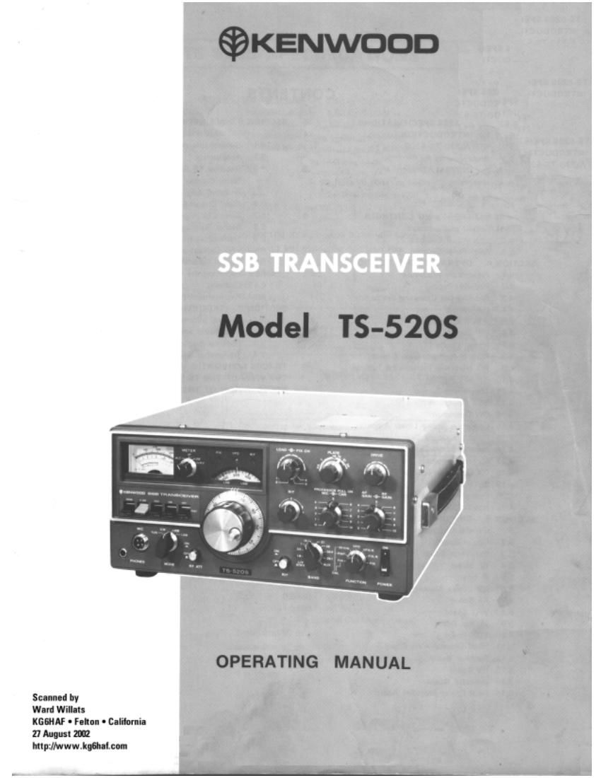
Kenwood TS 520 S Service Manual 2

This is the 49 pages manual for Kenwood TS 520 S Service Manual 2.
Read or download the pdf for free. If you want to contribute, please mail your pdfs to info@audioservicemanuals.com.

Page: 1 / 49
left right
Kenwood TS 520 S Service Manual 2

Extracted text from Kenwood TS 520 S Service Manual 2 (Ocr-read)


Page 2

CONTENTS

TS-5205 SPECIFICATIONS ............... 3
SECTION 1. INTRODUCTION ............................ 4
1.1 KENWOOD TS-EZOS
1.2 Requirements for Operation
SECTION 2. INSTALLATION .......................... I ...... G
2.1 Unpacking »
2.2 Operating Location
2.3 Cabling
SECTION 3. OPERATING CONTROLS ................. 9'
3.1 Front Panel Controls I
3.2 Side Panel Controls
33 Rear Panel Controls
SECTION 4. OPERATING INSTRUCTIONS...
4.1 Preliminary Procedure
4.2 Receiver Tuning
4.3 Reading the Operating Frequency
4.4 Calibration
4,5 WWV Reception
4.6 RF Gain
4.7 Noise Blanker
4.8 AGC (Automatic Gain Control)
4.9 RIT (Receiver Incremental Tuning)
4.10 RF ATT
4.1 1 Transmitter Tuning
4.12 853 Operation
4.13 CW Operation
4.14 Operation with a Linear Amplifier
4.15 Fixed Frequency Operation
416 Internal Cross Channel Operation
4.17 Mobile Operation
4.18 DX Operation (Use of Processor Pull on)
4.19 SSTV Operation
4.20 Operation with a Phone Patch
4.21 Novice Operation
SECTION 5. CIRCUIT DESCRIPTION .................. 26
5.1 General Description
5.2 Carrier Board
5.3 Generator Board

5.4 RF Board
55 IF Board
5.6 NB (Noise Blanker) Board
5.7 AF Board

5.8 VFO Board

5.9 Marker Board

5.10 VOX Board

5.11 Fixed Channel-AVR Board .
5.12 Rectifier Board

5.13 HV Board

5.14 Indicator Board .
5.15 Final Power Amplifier Board

SECTION 6. MAINTENANCE AND
ALIGNMENT ..................................... 34

6.1 General information

62 Accessories

63 Receiver RF Section Alignment

6.4 Noise Blanker Board Alignment

6.5 lF Board Alignment

6.6 Fixed Channel-AVR Board Alignment

6.7 Drive Coil Alignment

6.8 Carrier Balance Adjustment

6.9 Transmitter Neutralization

6.10 VFO Calibration

6.11 Crystal Calibrator Alignment

6.12 Replacing the Fuse

6.13 Cleaning

6.14 Replacement Parts _
SECTION 7. TROUBLESHOOTING ....................... 41

7.1 General information

7.2 Transmitter and Receiver Circuits

7.3 Receiver Section

7.4 Transmitter Section
TS-SZOS SCHEMATIC ............................................. 43
TOP VIEW OF THE TS-5205 ..........
BOTTOM VIEW OF THE TS-5205 ..

.. 44

Page 35

llll

SSB FILTER

\ Install the I
i filter here.

Move the brown lead from
the SSE terminal to the
CW termlnal.

VG-SSQSC

Fig. 30 Installing the Accessory CW Filter

Reconnect the VR mounting hardware and replace the
covers. If the speaker lead was disconnected, be sure to
reattach that also.

I INSTALLING THE DC-DC CONVERTER lDS-1A)

1. Remove the patch plate located on the rear panel of
TS-5ZOS.

2. Secure the DC-DC unit to the rear panel using the four
tapping screws supplied with the unit.

3. Select the correct color coded lead from the DC-DC unit
making sure that the color code corresponds to that of
the lead connected to the DC-DC terminal board
adjacent to the power transformer.

Solder the lead onto the terminal board.

I REMOTE CONNECTIONS

Figure 32 shows the REMOTE connector, This 8-pin plug
can be used for attaching linear amplifiers. or other external
accessories to the transceiver.

Rear panel of T575205

Patch plate
l V E
l \ E \b
5: 5 3
W Rear panel
Ll U
:13 @ Final box
00 o 0 o L...
"E O 0 terminal board
0


ALC input

Stand by
input

REMOTE

, 1

ALc input

To an external speaker
(3 s2)

The view seen from
the rear panel

Fig. 32 REMOTE Connector

35