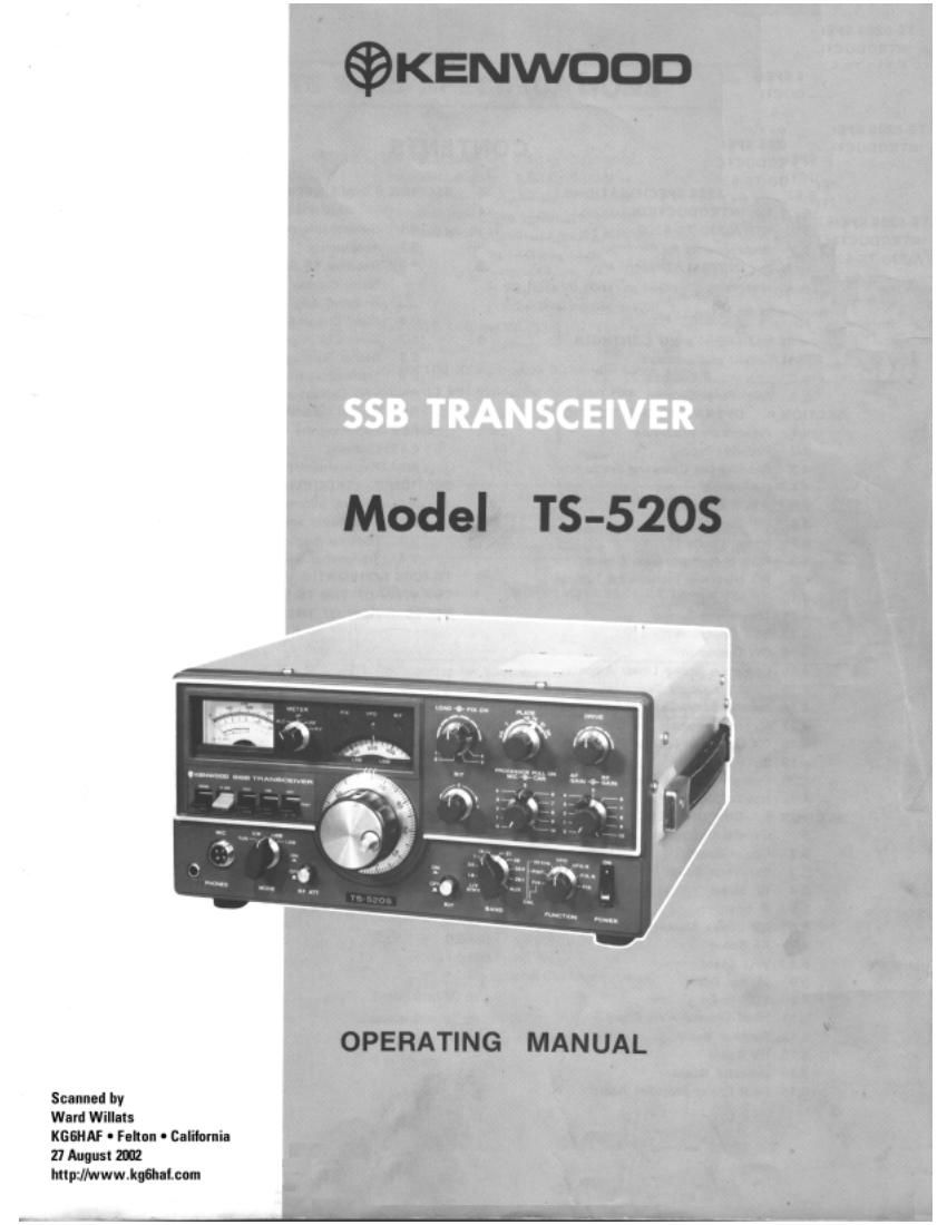
Kenwood TS 520 S Owners Manual

This is the 48 pages manual for Kenwood TS 520 S Owners Manual.
Read or download the pdf for free. If you want to contribute, please mail your pdfs to info@audioservicemanuals.com.

Page: 1 / 48
left right
Kenwood TS 520 S Owners Manual

Extracted text from Kenwood TS 520 S Owners Manual (Ocr-read)


Page 2

CONTENTS

TS-5205 SPECIFICATIONS ............... 3
SECTION 1. INTRODUCTION ............................ 4
1.1 KENWOOD TS-EZOS
1.2 Requirements for Operation
SECTION 2. INSTALLATION .......................... I ...... G
2.1 Unpacking »
2.2 Operating Location
2.3 Cabling
SECTION 3. OPERATING CONTROLS ................. 9'
3.1 Front Panel Controls I
3.2 Side Panel Controls
33 Rear Panel Controls
SECTION 4. OPERATING INSTRUCTIONS...
4.1 Preliminary Procedure
4.2 Receiver Tuning
4.3 Reading the Operating Frequency
4.4 Calibration
4,5 WWV Reception
4.6 RF Gain
4.7 Noise Blanker
4.8 AGC (Automatic Gain Control)
4.9 RIT (Receiver Incremental Tuning)
4.10 RF ATT
4.1 1 Transmitter Tuning
4.12 853 Operation
4.13 CW Operation
4.14 Operation with a Linear Amplifier
4.15 Fixed Frequency Operation
416 Internal Cross Channel Operation
4.17 Mobile Operation
4.18 DX Operation (Use of Processor Pull on)
4.19 SSTV Operation
4.20 Operation with a Phone Patch
4.21 Novice Operation
SECTION 5. CIRCUIT DESCRIPTION .................. 26
5.1 General Description
5.2 Carrier Board
5.3 Generator Board

5.4 RF Board
55 IF Board
5.6 NB (Noise Blanker) Board
5.7 AF Board

5.8 VFO Board

5.9 Marker Board

5.10 VOX Board

5.11 Fixed Channel-AVR Board .
5.12 Rectifier Board

5.13 HV Board

5.14 Indicator Board .
5.15 Final Power Amplifier Board

SECTION 6. MAINTENANCE AND
ALIGNMENT ..................................... 34

6.1 General information

62 Accessories

63 Receiver RF Section Alignment

6.4 Noise Blanker Board Alignment

6.5 lF Board Alignment

6.6 Fixed Channel-AVR Board Alignment

6.7 Drive Coil Alignment

6.8 Carrier Balance Adjustment

6.9 Transmitter Neutralization

6.10 VFO Calibration

6.11 Crystal Calibrator Alignment

6.12 Replacing the Fuse

6.13 Cleaning

6.14 Replacement Parts _
SECTION 7. TROUBLESHOOTING ....................... 41

7.1 General information

7.2 Transmitter and Receiver Circuits

7.3 Receiver Section

7.4 Transmitter Section
TS-SZOS SCHEMATIC ............................................. 43
TOP VIEW OF THE TS-5205 ..........
BOTTOM VIEW OF THE TS-5205 ..

.. 44

Page 16

PIN FUNCTION PIN FUNCTION
Normally open
1 Ground 5 relay contact
ALC Veedback
2 No connection 6 ALC threshold level
approx. - 6V
3 Normally dose" 7 No connection
relay contact
External speaker
4 Ground 8 Load impedance
4 ~ 169

I EXTERNAL VFO CONNECTOR (@ on Figure 7)

This 9-pin connector provides a means of interconnecting
the KENWOOD VFO<5205. another external VFOt The
interconnecting cable is provided with the VFO-SZOS. The
9»pin jumpered VFO plug provided with the TS-SZOS must
be inserted in this socket for normal transceiver operation.

PIN FUNCTION PIN FUNCTION
. Calibratorsignel
1 VFO signal 6 (9V DC)
2 VFO signal shield 7 No connection
9V DC to internal
3 GM 8 vro (pin 9)
9 9V DC to external
4 12.6V AC VFO
Relay voltage
5 (+ on transmit)

I so SWITCH (ti) on Figure 7)

The SG slide switch controls the screen grid voltage on the
final tubes. For tuning or neutralizing the TS-SZOS you can
set the switch to the OFF position. Turn the switch back to
the ON position for normal operation. The $6 voltage is on
when the switch is up and off when the switch is down.

I GND (Ground) LUG (0 on Figure 7)

To prevent accidental shocks from the chassis, as well as in-
terference, connect a good earth ground to this lug.

I AC VOLTAGE SELECT SWITCH (Q on Figure 7)

This slide switch switches the primary of the power
transformer to select 120 or 220V AC operation.

I EXTERNAL RECEIVER ANTENNA JACK ((9 on
Figure 7)

This is an antenna connector to which an external receiver,
for example, a sub-receiver, is connected.

I RECEIVER ANTENNA SWITCH (Q on Figure 7)

This switch connects the antenna to the TS-5205 at the
NORMAL position and to the external receiver at the REC
ANT position.

Example: Changing power voltage from 220V to 120V.

Remove screw and Switch stopper

stopper plate

220v 220V
Stopper plate

to opposite side

Lock lever by attaching
stopper plate to opposite
side screw

Fig. 8 Changing Power Voltage

16

Page 19

USB ....... Use the procedure described above with the
MODE switch turned to USB. Use the USB
(right-hand) dial pointer.

CW ........ Set the mode switch to TUNE to zero beat the
marker signal. Then, turn the main dial and ca-
librate the frequency using the center dial pointer.

If the TS-SZOS has a CW filter installed, tune the VFO for
maximum S-meter deflection when receiving the marker sig-
nal. Calibrate the dial scale to the center pointer as
described above.

I CALIBRATING THE TS-SZOS TO A FIXED
CHANNEL FREQUENCY

Turn the FUNCTION switch to CAL-FIX to calibrate the
TS~520$'s VFO to a fixed channel frequency. Tune the VFO
to the channel frequency selected and zero beat the
generated marker signal. At zero beat the VFO and crystal
frequencies coincide.

By calibrating the VFO for normal operation, as described
above, the VFO can be used as a frequency standard for
netting accessory fixed channel crystals,

I CALIBRATING THE TS-5205 WITH THE VFO-SZOS

Turn the FUNCTION switch to CAL-RMT to calibrate the
TS-SZOS with the VFO-SZOS a receiver, or another remote
VFO, Tune the remote VFO to the frequency selected on the
TS-EZOS and zero beat the generated marker signal.

At zero beat, the TS-EZOS and remote VFO frequencies
coincide.

By calibrating the TS-EZOS for normal operation. as
described previously, the TS-SZOS can be used as a
frequency standard for calibrating the remote VFO.

l CALIBRATING THE TS-EZOS MARKER TO WWV

To check that the marker signals are correctly adjusted, beat
the calibrator signal against WWV at 15 MHz. Receive
WWV at 15 MHz as described in Section 45. Turn the
FUNCTION switch to CAL-25 kHz and the MODE SWITCH
to TUN. The calibrator signal and WWV signal should over-
lap and zero beat at the zero marking on the sub-dial. If they
do not, adjust the calibrator to zero beat with TCI on the
MARKER (X52-0005-Ol) board.

4.5 WWV RECEPTION

The TS-SZOS will receive WWV at 15 MHz when the BAND
switch is turned to WWV and the sub-dial is turned to zero.

The DRIVE control does not tune the transceiver for WWV
reception.

4.6 RF GAIN

RF GAIN is controlled by changing the voltage of the AGC
circuit. Adjust the RF GAIN knob so that the S-meter does
not cause excessive deflection. This minimizes the noise dU<
ring reception and allows the S-meter to indicate the correct
signal strength. For normal operation, this knob should be
turned fully clockwise for maximum sensitivity.

4.7 NOISE BLANKER

The TS-SZOS has a sophisticated built-in noise blanket
designed to reduce ignition type impulse noise. The noise
blanker is particularly important for mobile operation. When
necessary activate the noise blanker circuit by flipping the
NB switch up.

4.8 AGC (AUTOMATIC GAIN CONTROL)

Set the AGC switch to the position appropriate for the
received signal. Generally for $53 recepiton set the AGC
switch to SLOW, for CW reception set the AGC switch to
FAST, and for reception of a very weak signal the switch
may be set to off.

4.9 RIT (RECEIVER INCREMENTAL
TUNING) '

With the RIT switch turned off the TS-SZOS receives and
transmits at the same frequency. At times the received sig-
nal may drift off frequency and become less intelligible.
When this happens, flip the RIT switch up to activate the RIT
circuit and return the received signal to an intelligible state
using the RIT control. The RIT control varies the receive
frequency about :3 kHz. The RIT circuit has no effect on
the transmit frequency. When the FIIT switch is turned on
the RIT light is illuminated, Be careful to turn the HIT to the
OFF position when returning to normal transceive operation
to prevent unintentionally transmitting and receiving on
different frequencies.

VR2 on the FIXED CHANNEL-AVR board adjusts the zero
point of the RIT control (see Section 6.6).

19