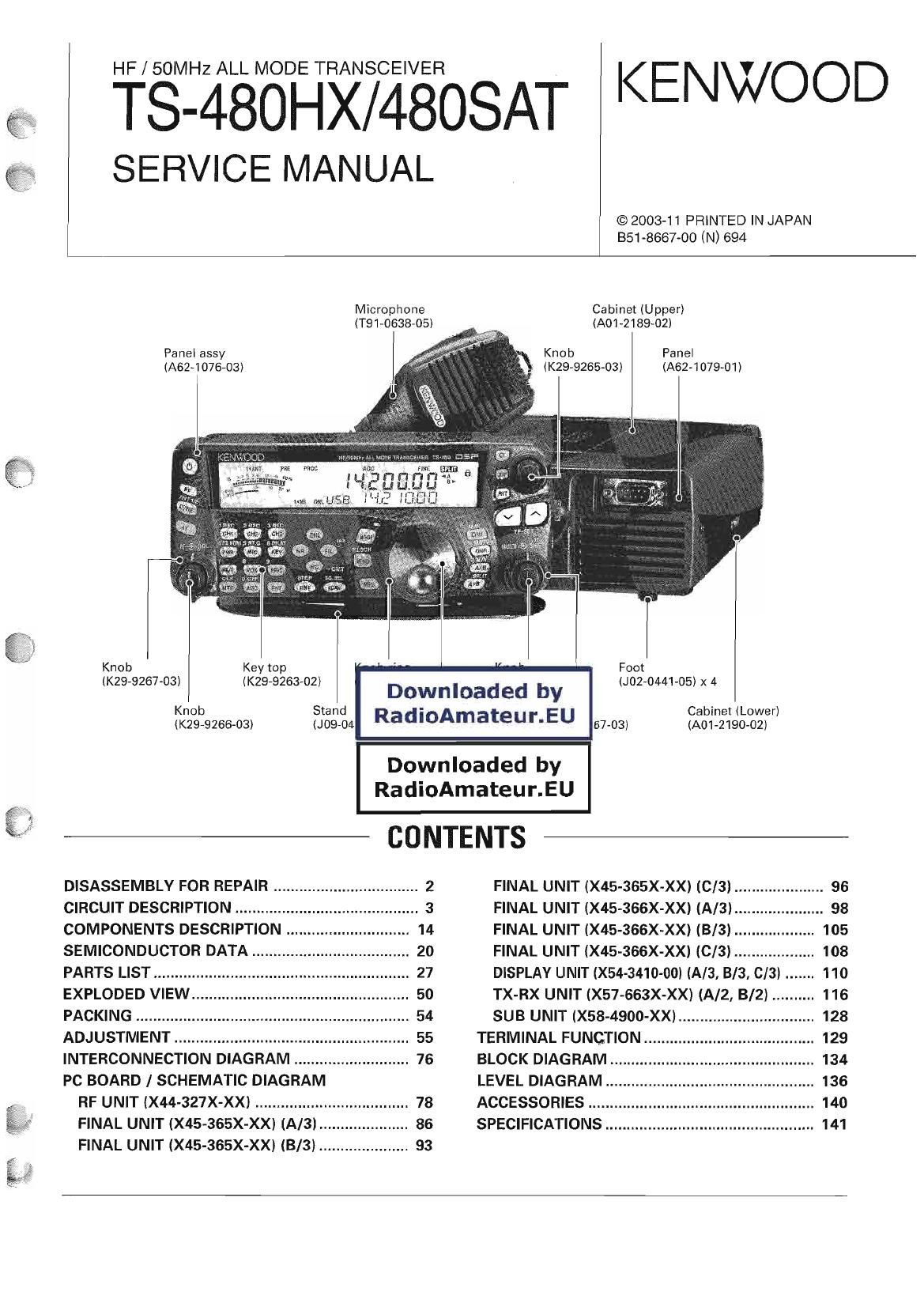
Kenwood TS 480 HX TS 480 SAT Service Manual

This is the 142 pages manual for Kenwood TS 480 HX TS 480 SAT Service Manual.
Read or download the pdf for free. If you want to contribute, please mail your pdfs to info@audioservicemanuals.com.

Page: 1 / 142
left right
Kenwood TS 480 HX TS 480 SAT Service Manual

Extracted text from Kenwood TS 480 HX TS 480 SAT Service Manual (Ocr-read)


Page 2

TS-480HX/4808AT

DISASSEMBLY FOR REPAIR

How to remove the torque changeover Ie- Cautions for mounting the main dial knob

ver (602-0898-04) (K21 -1 105-03)

1 Turn the lever section of the torque changeover lever to Confirm that the lever section of the torque changeover
the right (@l lever is in the fully turned left position (Torque OFF) before

2 Insert the tip of a flat-head screwdriver into the recessed mounting the main dial Knob

part of the torque changeover lever (3))

3 Lift the torque changeover lever using the tip of the flat-
head screwdriver ((3))
Caution: Be careful not to damage the torque changeover
lever when lifting it

4 Turn the lever section of the torque changeover lever to
the right, as in the position described in step 3 (@l

5 Lift the torque changeover lever and remove it from the
panel ASSYi

Cautions for replacing the torque change-
over lever

Apply the dry-surf 2400 onto the front and rear surfaces
after replacing the torque changeover lever (Do not apply the
dry surf to the lever section )

\ Apply the dry-surf 2400
onto the front and rear
surfaces of the torque (*

changeover lever.

How to mount the torque changeover le-
ver (602-0898-04)

1 Insert the torque changeover lever into the mounting loca-
tion so that the three tabs align with the torque
changeoverslots (Figfl)

2 Turn the lever section of the torque changeover lever to
the left while pressing the surface of the lever as shown in
the Fig 2, and mount it onto the panel ASSY

Page 9

TS-480HX/4808AT

CIRCUIT DESCRIPTION

3) Recording a message

The signal sent from the microphone is output from pin 11
to pin 10 of the analog switch (IC219), where it enters into
the CODEC (IC217) The signal sent from the CODEC enters
pin 13 of the DAC (lCZi 2), and is then sent from pin )4 to the
optional unit (VGS-i) to be recorded

I Constant received audio recording function
1) Recording

A part of the received audio signal is sent from the CODEC
(lC217) to pin 13 of the DAC (lCZl 2), and is then sent from pin
14 of the DAC to the optional unit (VGS-i) to be recorded The
recording level is automatically compensated to become con-
stant and you cannot randomly change the level

2) Playback

The output signal (VOl) sent from the optional unit (VGS-i)
passes from pin 1 to pin 2 of the DAC The signal passes
from pin 8 to pin 9 of the analog switch (IC219), and is then
mixed with the input signal of the AF amplifier (IC734) The
DAC (lC2i2) controls the volume

I Other functions
1) Playing a message (monitor)

The output signal (VOl) sent from the optional unit (VGS-i)
passes from pin 1 to pin 2 of the DAC The signal passes
from pin 8 to pin 9 of the analog switch (IC219), and is then
mixed with the input signal of the AF amplifier (IC734) The
DAC (lC212l controls the volume

2) Playing a pre-recorded voice message
The above-mentioned signal path is also used for playing a
pre-recorded voice message

iC218iA/2)
DET [\
- AFOUT
l/
|C734
AnIfICZJ 19sw 'C217 AF AMP
12 9 CODEC
MIC-j mm
11
MIC {/0 1° DAC
13 21 l 22
PKD 1 @I/ 2 W» FMOD
ANI or 24 L 23
5 |C220 M SMOD
DRO-4-i 3 DSP 16 h 15 AND
DRO {/0 l
6 13 14 DRM
8 I 9 V08 VOAF 2 l vor Option
voo L-0/<3 vw 1 VGS'l
V00 TX-RX unit (A/2)

Fig. 8 Signal path before/after the CODEC

Modulation Circuit

The modulation signal processed at the DSP is sent to the
modulation circuit The circuit receiving the modulation signal
is different between FlVl mode and 888/ AM/ FSK model

1) 883/ AM/ FSK mode
The modulation signal sent from the DAC (IC212) enters
the balanced modulator (lCGZl) after inverting the phase at
0625 The TC 695MHz transmission signal sent from the bal-
anced modulator is amplified at 0621 and is then sent to the
next stage
- AM mode
The DC voltage is applied to the pin 1 of the balanced
modulator via D624 With the DC voltage, the AM carrier
is generated since the balanced modulator becomes un-
balanced
° FSK mode
In conventional FSK mode, the frequency of the carrier
was changed with the external keying signal This trans-

ceiver generates the FSK signal by changing the single
tone (AF) generated at the DSP The balanced modulator
performs the same operation as 888 model

- CW/FlVl mode

The necessary carrier wave is obtained by making the bal-
anced modulator lose balance

DC for TXvRX .
((15:35 AM/FSK mt W2)
SSB/AM/FSK \ -> DSB OUT
Mod IN 10521 10.695MH2
Balanced
MOd CAR

/ Differential 10.695MH2

0.625 input

(2/2)

Fig. 9 SSB/AM/FSK mode modulation circuit

Page 112

1

, _ «
.
. W
.. .. w M1
M
. W .
.. . . .. w
- x .- . . .. 1.1...111- 1 1 1%---- 1 1 ,1. 1-
. . . M w W
W. M . . .. w _.
m ., M W M W
W ) . _ .1 .u . . , w
m 9 M .M . H . w A
1 w: 1.: 0. . . W. W w w
.w 7 _. . .2 .. .111111.1-_.--_..111-.1.11-4111+1.111.... 111-1 5 . .. .. . . . .1
.. 7 w 5. J. W .5 w
.W 00 . .. 5 x w m 5
W n.... . . . W. W w
m 2 . . W h
,. 7. w W
- w U _
w 1.111 1 fi _ 1.5.1 -4, m -11
M e m H H H l D fl
_. .W w 7 7 7 7 4 #
M e M 5 7 w
W, o. _
M .um N. 6 7 8 9 W: . fi
1- 4 1 1 1 I 111111.[. R; 5 6 1 . .5: . 4.11 11
w .m m 4 _ V . 7
W F M M M a M m Rim M _
5 B .1... 1 . .5 .
... . 2 3 4 5 6 7. w _
. C , f. O O 0 0 ob. m . W
.1 1.147111111111 I w We , fl w 5
M 3.. 1.1%.? .._ -4211---
H l W m D1 .l
W B M w 4 w m .9» wk... m M
I A 5
3 1a. 11L. . m w
M M H N. m m m m m m 1 5
( , Q5... _ 4.111115 5
11.1--- 1 . .. . .11, E. ,. ., -1111 R. _ M .
w W . w . .m. .. .. . :52: . M m N. M
5. 0. .317 .._.n .6 mm 0 .. .3; .. w W m .
W 1. MN... 9. We . . _ nzu . .. M W
4 _1$Emmu. _, E. 1... .. ., u M m
_ a .. 1.- 11,411...- . . 11
m 2w 0 EEPWA . 2 ._ . .141... m .5 m e . A .
41 44 41.41 I 1!! 4 Ln .1. 1... t 1.. .1... . Shut...» 4; L..« x. 4 1.411 :1. 4.. .111 Fain? 1 4. 1 1. 1 m v. 1w W 1 M .
. 5 _ . .. e . s T I- . 5.... 1 .
. X m .4 m V». H . w W
w ( N up w D. O w _ ~
. _ .. w m . El _ .
M T 5. r. w » 0 ,. m M
W H w. M C _
R m . 4.. H m m m W 5 F
U W W PM _._, W . v V 5 5
111111... .-.m. .1 1.111)--.- mm W , M
M VA- .u m. . W 11 1 x- w 51.4 4 1.441.-.. 1
M L ,. H _ .. . 5 M
W P . . m . . _ H ,
S . h . W N W .2 W
_.. I H w M M u . 1
W D m g .5 . m w W1
V . m M fl _
. _ a . .

11
12
13
14