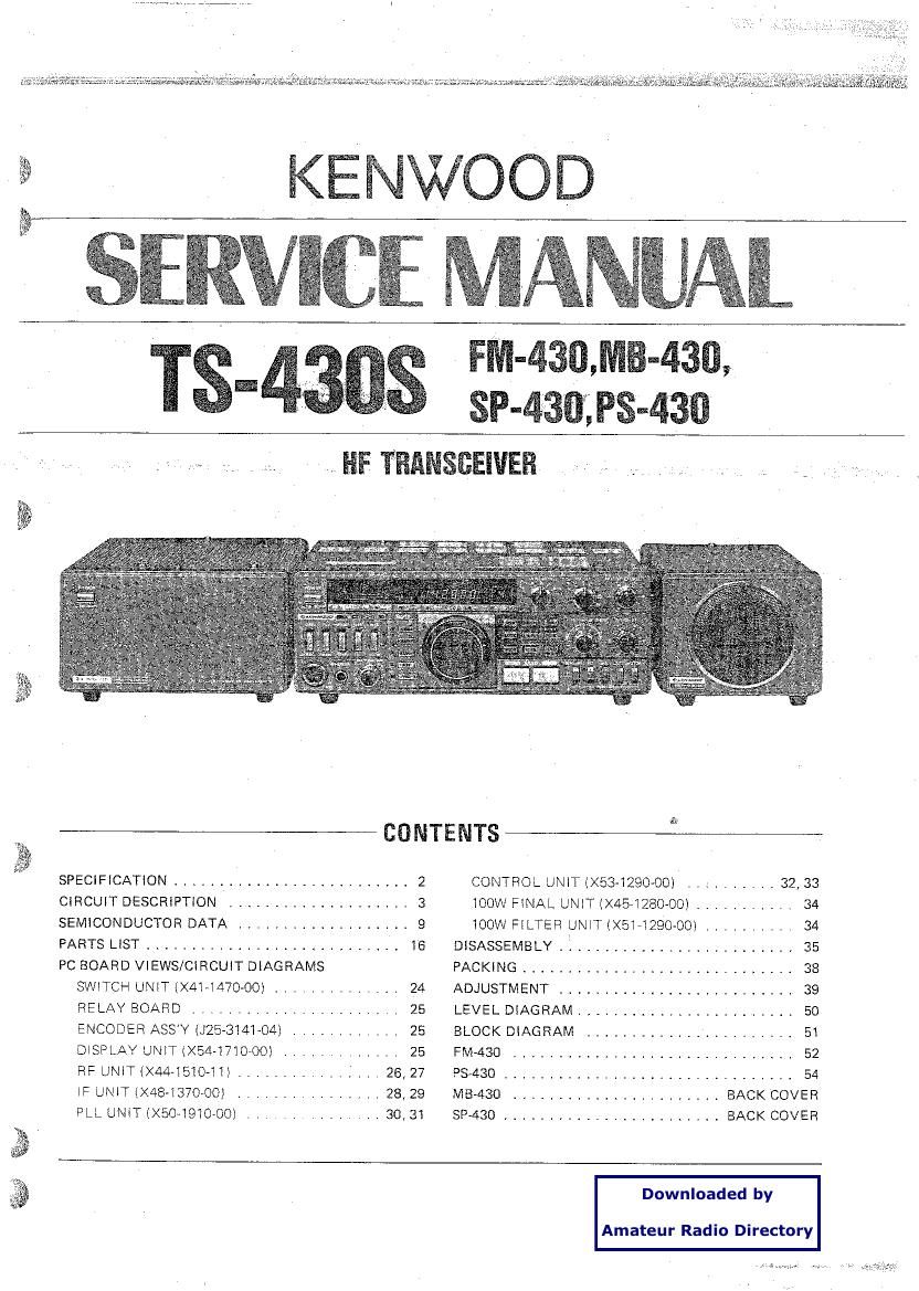
Kenwood TS 430 S Service Manual

This is the 54 pages manual for Kenwood TS 430 S Service Manual.
Read or download the pdf for free. If you want to contribute, please mail your pdfs to info@audioservicemanuals.com.

Page: 1 / 54
left right
Kenwood TS 430 S Service Manual

Extracted text from Kenwood TS 430 S Service Manual (Ocr-read)


Page 1

WIS-$33. 43%,
SP-éSfl;F3-43fl

I, HF TRANSBEIVER

SPECIFICATION .......................

CIRCUIT DESCRIPTION .................

SEMICONDUCTOR DATA ................

PARTS LIST ..........................

PC EOARD VIEWS/CIRCUIT DIAGRAMS
SWITCH UNIT (X4I-I470-OO) ... ........
RELAY BOARD .....................
ENCODER ASSY (QB-314104) ........ .
DISPLAY UNIT IX54-I7'IOVOO) ..... . .. .
RF UNIT (X44v15IO-I II ..............
IF UNIT IX48-IB7000I ...............
PLL UNIT(><50-19IOVOO)

CONTENTS
... 2 CONTROL UNIT IX534290_00I ..,- ....... 32, 33
... 3 wow FINAL UNIT Ix45I280-00I ........... 34
... 9 wow FILTER UNIT IXSI-IQQO-OOI .......... 34
. . 16 DISASSEMBLY ,L ........................ 35
PACKING .............................. 38
.I 24 ADJUSTMENT .......................... 39
25 LEVEL DIAGRAM ........................ so
25 BLOCK DIAGRAM ....................... 5I
., 25 FM-430 ............................... 52
26, 27 93430 ................................ 54
28, 29 NIB-430 ....................... BACK COVER
30, 31 SP-430 ........................ BACK COVER

Downloaded by

Amateur Radio Directory

Page 2

E§u439§

[GENERAL]

Transmitter Frequency Range:
Receiver Frequency Range:
Mode:

Antenna Impedance:

Power Requirement:

Power Consumption:

Dimensions:
Weight:
[TRANSMITTER]
Final Power Input:

Downloaded by

Amateur Radio Directory

SPECIFICATIONS

160, 80, 40, 30, 20, 17*, 15, 12*, 10 meter Amateur bands
150 kHz to 30 MHz

A3J (LSB, USB), A1 (CW), A3 (AM), F3

50!)

12.0 to 16.0 V DC(13.8 V nominal)

20A approx. in transmit mode

1.2A approx. in receive mode

270 (10.6)W x 96 (3.8)H x 275 (10.8)D mm (inch)

6.5 kg (14.3 lbs.)

M0 888 cw FM AM
Band
160m - 1 5m band 250WPEP zoowoc - 60W
10m band 250WPEP ZOOWDC 120w 60W
Modulation: 553 = Balanced Modulation

Carrier Supression:

Unwanted Sideband Suppression:
Harmonic Content:

Maximum Frequency Divination (FM):
Microphone Impedance:
[RECEIVER]

circuitry:

Intermediate Frequency:

PM = Variable Reactance Direct Shift
(with FM-430 optional accessory)

AM = Low Level Modulation (IF stage)

Better than 40 :18

Better than 50 dB

Less than -40 dB

3:5 kHz (with FM-430 optional accessory)

5001210 50 k!)

SSB, CW, AM = Double conversion Superhaterodyna
FM =Triple Conversion Superhstarodyne

1 st IF _ 48.055 MHz

2nd IF 8.83 MHz

3rd IF :45?) kHz (only FM)

Sensitivity:
Frequency
150kHz - SOOkHz SOOkHz - 1.8MHz 1.8MHz -- 30MHz
Mode

SSB/CW(10 dB S/N) Less than 1 )N Less than 4 av Less than 0.25 1.1V

AM(10 dB S/N) Less than 13 V Less than 40 11V Less than 2.5 uV

FM (30 dB S/N) - - *Less than 1 [N
FM (12 dB SINAD) - - *Less than 0.4 uV

Image Ratio:

* with FM-430 optional accessory
More than 70 dB (18 to 30 MHz)
More than 50 dB (FM~3rd image ratio)

IF Rejection: More than 70 dB (1.8 to 30 MHz)
Selectivity:
Selectivity
-6 dB -60 dB
Mode

SSB/CW 2.4 kHz 4.4 kHz
AM *1 6 kHz 12 kHz
FM *2 15 kHz 32 kHz

" 1 with YK-88A optional filter
* 2 with FM-430 optional accessory

Frequency Stability:

Frequency Accuracy:

RIT Variable Range:
Audio Output Impedance:
Audio Output Power:

Will transmit on the new 30, 17 and 12 meter bands, Diodes have been installed to prevent accidental

transmission. They may be removed easily when government authorization has been granted for Amateur

operation.

Better than t 30 x 106 (0!) to +500), Within :200 Hz from 1 to

60 minutes after turn~on: within :30 Hz any 30 minutes period
thereafter

Better than 10 x10"6

More than i 1 kHz

4!) to 16!.)

More than 1.5W across 8!) (at 10% distortion)

Note: Circuit and ratings subject to change without notice due to developments in technology.

LL

Page 43

13-4305
3 ADJUSTMENT

§ Measurement Adjustment
Item Condition Test Specification/Remakrs
equipment Unit Terminal Unit Part Method
13. IC meter 1) FREQ $14,175.0kHZ lC ANT Filter VRS 14A
MODE : CW meter
CAR LEVEL control : (Power
current drain 17.5A meter)
Connect Ammeter
CD : EXT power supply (-9
terminal
6 L Power connector ® terminal
STBY : SEND
14 ALC 1) MODE : USB ALC, IF VR12 Set to ALC
meter MIC LEVEL control : MIN meter meter starting

METER SW : ALC point.

STBY : SEND

2) FREQ : 14,175.0kHz Power ANT

AG output: 1kHz, 5mV meter

MIC LEVEL control : (509)

; Set to ALC meter starting ,
Point.

AG output: +6dB IF VR11 Adjust for maxi-
mum ALC scale
reading.

15. Speech 1) MODE : USB AM V.M IF TPZ IF VR7 Level should be the 140mV (Reference
processor MIC LEVEL control : MIN same between ON value)

AG output: 1 kHz, IOmV and OFF.

PR'oc SW: ON and OFF

STBY : REG

3 16. CW side 1) MODE : CW AF V.M Rear EXT. IF VRIO 0.63V/Bn
by tone AF GAIN control : 12 oclock Oscillo- panel SP

VOX SW : MAN scope

STBY : HEC ' AF

Connect KEY to KEY jack and dummy

close the key contacts. load

Downloaded by 45

v~*~"""" ' > , -. Amateur Radio Directory

Page 45

ADJUSTMENT

TS-4305

Turn the VFO
counterclockwise

. start and at return to the

The "Beeper" sounds at the

starting frequency.

The scan stops at the fre-
quency preset in M.CH : 6.

3) HOLD SW:OFF

The scan resumes from the
displayed frequency.

Item Condition Operation check Item Condition Operation check
6. Memory 1) M.CH SW : 'l FREQ: 14,000.0kHz 10. A=B DIE] SW : OFF "VFO B" display lights.
recall (2) (E SW : ON The "Beeper" sounds. (Function) SW : OFF
sw ; OFF
2) Turn the VFO The display shows normal FUNCTION : B
both clockwise and frequency control. FREQ : 7,000.0kHz
counterclockwise. MOREJJ'iB _______________
3) SW : ON FREQ L 14,000.0kHZ FUNCTION : A "VFO A" display lights.
The tone sounds simultane- FREQ : 14,000.0kH2
ously. MODE : USB
7. Memory 1) M.CH SW : 8 The frequency display 2) FUNCTION : A FREQ : 14,000.0kHz
erase STBY : REC clears fier the BAND SW : ON MODE : USB
Place the SW: ON and SW keys are FUNCTION : B FREQ: 14,000.0kH2
While depressing either UP released. MODE ; USB
5 or DOWN BAND SW key. The "Beeper" sounds.
8. Memory 1) (E SW : ON M.CH : 1->2->3->4 11. UP/ 1) Connect a microphone When the 100Hz digit
scan [ DOWN (MC-60A or MCAZS). changes, the 100 Hz
7<-6<-5 (Micro Momentarily depress upper frequency is dismayed
Displays the frequencies phone) the "UP" key several after ten keyapresses.
and modes in Item 5. 1). times.
3 Program 1) SW ; OFF The scan starts from M.CH : 2) Hold the "UP" key on. The frequency continuously
scan SW : ON 6 (FREQ : 14,000.0kHz) advances forward after a
PG. SCAN SPEED to M.CH :7 (FREQ: SHIFT SPEED/SEC. a short delay.
Pot. : MIN. 14,010.0kHZ).
When the frequency reaches 3.2k ______ __
14,010.0kH2, the
scan returns to 14.0001)
kHz and starts again, 0.8):
The scan speed is approx.
5OOHZ/sec. The "Beeper" T
sounds at the start and at it: 4 H SEC-
return to the starting '
frequency. 3) Momentarily depress the When the display of 100Hz
___________________ "DOWN" key. range changes, the 100H2
PG. SCAN SPEED Pot. : The scan speed is approx. lower frequency is displayed
MAX 2.5kHz/sec. (five times after ten keyepressed.
faster then MIN).
2) SW : ON The scan stops 4) Hold the "DOWN" key The frequency continuously
___________________ on. advences backward after 3
Turn the VFO clockwise. The scan repeats within the short delay.
preset mnge from M.CH : 6 .
-v M.CH 2 7 12. Lock 1) SW : ON The frequency displayed

Turn the VFO both
clockwise and counter-
clockwise.

2) Depress both BAND UP
and DOWN keys.

3) Hold the microphone
(MOBOA or MCAZS)
"UP" and "DOWN" key
on.

at lock does not change.

47