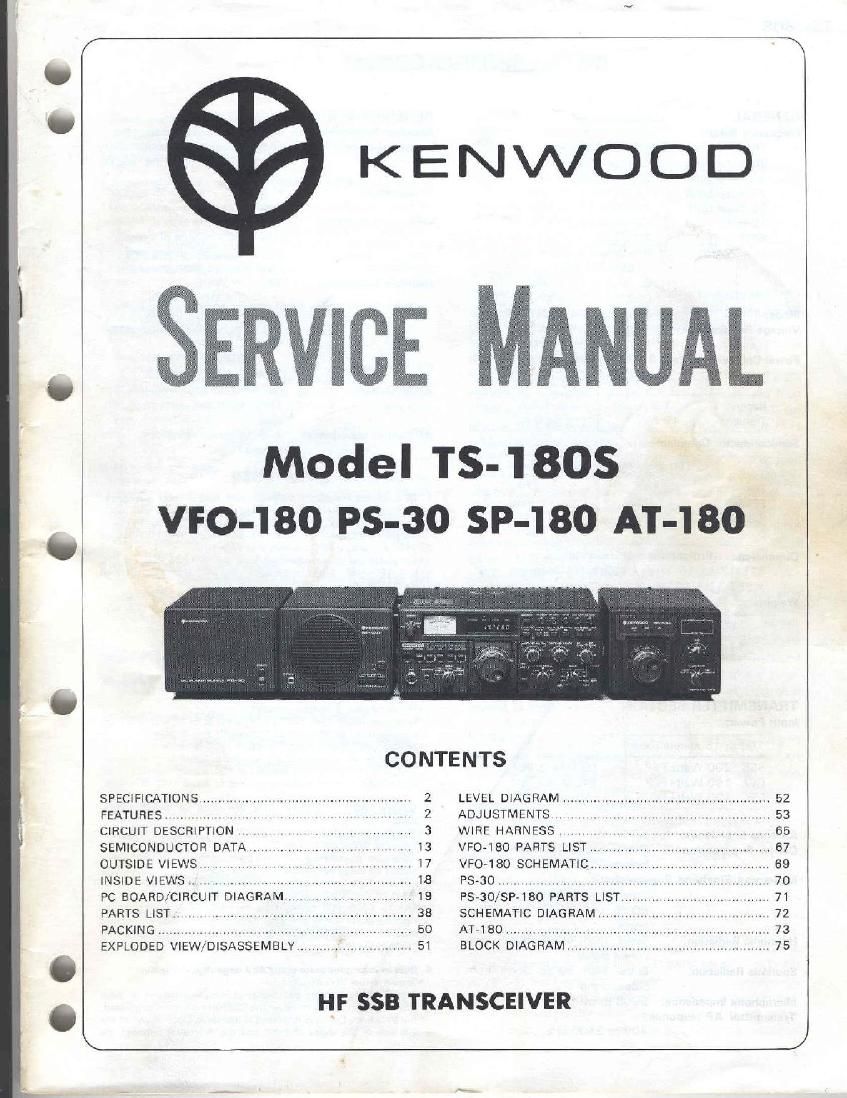
Kenwood TS 180 S Service Manual

This is the 78 pages manual for Kenwood TS 180 S Service Manual.
Read or download the pdf for free. If you want to contribute, please mail your pdfs to info@audioservicemanuals.com.

Page: 1 / 78
left right
Kenwood TS 180 S Service Manual

Extracted text from Kenwood TS 180 S Service Manual (Ocr-read)


Page 1

KENWOOD

~ A UM-

Model 154805
VFO-IBO PS-30 sP-Iso AT-Iao

SPECIFICATIONS
FEATURES.. .. V . .
CIRCUIT DESCRIPTION . r. H I ,
SEMICONDUCTOR DATA u .7 .
OUTSIDE VIEWS. . H . ,. .,.
INSIDE VIEWS .. ,. .. .I . ...
PC BOARD/CIRCUIT DIAGRAM.

PARTS LIST. .. V .. .I
PACKING ........................................
EXPLODED VIEW/DISASSEMBLY..

2 LEVEL DIAGRAM .........................
2 ADJUSTMENTS H V. .
3 WIRE HARNESS
. I3 VFO-180 PARTS LIST,..
I I7 VFO-180 SCHEMATIC ..................
PS-30/SP-180 PARTS LIST. ,
SCHEMATIC DIAGRAMIWH .. . .. .. ., .. .
AT-180 .......................................
BLOCK DIAGRAM_ . I ., .. .. . ..


HF SSB TRANSCEIVER

Page 2

TS-1808

SPECIFICATIONS

GENERAL

Frequency Range:
160 meter hard
80 'rrsier band .
40 meter band .

.180 to 2.001%le
:3 hi) in 4.00112le
7 0010 7 31) NIH?
20 rreter band . . 14 00 to 14 35 NH:
15 rreterband ..2100tu 7145MH7
10 meter band .. .. 28.00 to 29 7O MH7
WNV ........... 1C 0 MH4 truceive 0'11 2
AUX 23Al\D. ..... A: 2.0 to 15 0 MHz 33:31]
500 kllz sand
B: 18.0to 18.5 MHZ
(I 21:.Oto 25.5 MHZ
Mode: SSHtAIiJl, (ZWEA' i. :SKEF')
Voltage Requirements: 1 1 OVDC to 1 GDVDC
[13 BVDC ro'ninnll
Power Consumption (at 13.3 VDC VSWR less than 1 5:11:

TSJBOITS-1 8051' T's-1808 (with DEC!

Receive 1.2 A 16 A
Transmit 19.6 A 20 A

Semiconductor Complement:

T5434: {TS 5051: Tsraos lwnh 1) Fuji

lrarststcrs 143 1 7 7
l-i:l S 2 l 26
ICS 33 53
Dimes 203 24 0

Dimensions: (Projections not included)
325112-13116'le1tiex133M) 1/4"thl_qn
x 287111451161deep

Weight:

TS-1801T3-18OSI I TS-I 805 lw'tn D.F,Ci

11,0 k9124.2|bsl 11.5 k9125.3|b$l

TRANSMITTER SECTION

Input Power:

160 to 15 meters band 10 meters band

$53 200 \Natis PFP
CW 160 Walls PEP
FSK 100 Walls DC

160 Watts PEP
1 40 Watts DC
50 Watts DC

5O Ohns

Car'inr better tran 40 dB clown
from the output s'gnal
Unwanted Sidebend Suppression:

Unwanted srdeband is bette' than
60 018 down from the output
signal

Better than 40 dB down f'om
output srgna

Better than 50 :18 down f'om
output signa

Microphone Impedance: 5000 to 50 k0

Transmitter AF response:

400 to 2600 kHz

Antenna Impedance:
Carrier Suppression:

Harmonic Radiation:

Spurious Radiation:

2

RECEIVER SECTION
Receiver Sensitivity:
image Rejection:

0.251tV S- NJN 0 dB or more
mage frequency better than
60 :13 down frorr the output
Signal
1- Irenuenny rs 8:) dB or more
down from crrtrm Signal
Wi1hin t1 kH7 during the his
hour after 1 minute of warmlip
Within 100 Hz during any 30
mrtha period alter war'rrup
SSE, CW WIDE

2.410121-6 dB?

4.2 kHzl-GO CB)
(2W NAH, FSK IWrtn optional iltcr
YK 88C?

0 5 k-lz 1v 6 (181

1 8 krill-60 dB)
More than 2 watts (with less than
13% drstoticrt into an 4 ohm

IF Rejection:

Frequency Stability:

Receiver Selectivity:

Audio Output:

loec.
AF Output impedance: 4 to 16 ohms Ispeaker or head-
phnnnm
FEATUR ES

1. DFC [Digital Frequency Control). with four unable memories.

'Merrrmies are usable In iraris'rlil Hill? In 'eceive rrrutles Spl lA
frequency ooeravm is possble wrth 18~1 808 V1 0 and any one ot
the an-rrruvics, witl- TS-1SOS VFO a'ru opiiunal VO 180 exit-rural
VFO, and Wth 3 DH: memory and VH)-1HO

OMcr'roics can s:urc ircqucnccs from the TS 1805 VFO, FIX CH,
and VFO-1 80 Ann, Irequancres can he translerrerl between
memories.

'MBIVIO'VSIIII paddle swrlches el :rw any h'" the rrrerrmry lrmirren-
cres to be tuned n 20-111 steps up or down slow or fast, with
recall 9 the original stoiec frequency.

2. High-performance solid-stun lhal.

~Na drppmg or loading Just dial uo the trcqucncy, pca< the d'ive
and npemte .

OHigh power. Wit) W PlPl150 W DC input on 160- 15 meters.
and 160 W PEP: l 40 W DC on 10 "101615.

OHighM I'FIIleIB, With large heatsinl:

'Hnai trans stors (two SFR17145, each with PC=250W1 a'c
manufactured by Nulorola it) Kenwrmds spurnlltmtlnrm.

'DOJble protection crcurts It the VSWF is more than 10.1 ,
transmit power 5 automatically reduced 1'.) smut 1.110 of rrurrr'al
Also. ii the temperature 0" the are 0 the transmit output col rises
abnormally, transmit power is recucec to about 110 0" normal.

3. Covers 160-10 meters. with provisions for WARC elect

tiom.

- iransceives on 160, 812176, 40. 20. " 5, and all at 10 meters.

ORecerves WWV on 10 MW

IAdaatable, by nsialling addrlional parteio three new bards, rl they
should be made available at tl-u World Adrmrrisirauvu Radio Con»
lerence, AUX 1 and AUX 2 as well as the WWV poswions are pro-
vided or the BA'\D swriclr or ["115 purpose.

the TS-1 808 Vic) covers more than 50 (Hz above and Below
each band: for MARS and other applrcatios, an thus wrli accorne
modate stuffs and expansions of existing hands t'rat might be
"ade a: WAHC.

4. Bait-in microprocessor-controlled large digital display.

0 'ruws aclual VFO frequent»;

IDigrtal display memory ard drsp ay oi frequency dlI'fchllCC. With
DSPW switch lurrred on Mien the DSPrDlFF 3w li::1 is depressed,
the treuuency that was crsaiaved 15 memorized and shown at the
let: side of the digital dsplav, and t're dilference between the

e
t

U

Q?