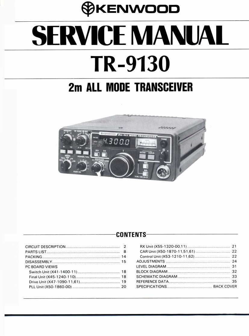
Kenwood TR 9130 Service Manual

This is the 38 pages manual for Kenwood TR 9130 Service Manual.
Read or download the pdf for free. If you want to contribute, please mail your pdfs to info@audioservicemanuals.com.

Page: 1 / 38
left right
Kenwood TR 9130 Service Manual

Extracted text from Kenwood TR 9130 Service Manual (Ocr-read)


Page 1

©KENwoon

SERVICE MANUAL

TR-9130

2m ALL MODE TRANSCEIVER

CIRCUIT DESCRIPTION...
PARTS LIST.
PACKING
DISASSEMBLY..
PC BOARD VIEWS
Switch Unit (X41 4400-1 1)..
Final Unit (X45»1240»1 10)....
Drive Unit (X47-1090-1 1,61)...
PLL Unn(X50-1860-OO) ..........

2
8

CONTENTS

RX Unit (X55~1320-00,I I) ...........
CAR Unit (X504 870-1 1,51,61)
Control Unit(X53~1210~1 1.62)....

.. 21
.. 22
.. 22

ADJUSTMENTS ................. 24
LEVEL DIAGRAM 31
BLOCK DIAGRAM .. 32

SCHEMATIC DIAGRAM
REFERENCE DATA.
SPECIFICATIONS...

.. 33
.................. 35
.. BACK COVER

Page 2

TR-9130

CIRCUIT DESCRIPTION

Receiver Circuit Configuration

The front end employs a dual gate MOS FET
01:38K76 and a helical resonator, L3. The first mixer
(02: 38K74i, followed by a Zestage MCF (Monolithic
Crystal Filter) XF1, provides excellent two-signal characterir
stics and high sensitivny.

The IF signal from the MCF is applied to both 888 and
FM circLiits. The 858 signal, having passed through the NB
(Noise Blanker) D7, D8 gate and crystal filter XF2
(1OH2.2$D) is amplified by IF amplifiers 011 - 013 and
demodulated into an audio signal by the product detector
D10 ~ D13.

In the NB circun, the signal from the MCF XFl is
differential by 03 and 04 and is then applied to
the second mixer, 05. The norse Signal, converted to a
455kHz signal, is limited by D2, D3, two-stage amplified
by 07, 08 rectified by D4, D5, and operates the NB gate
through 010, a SWitch transistor. 09 is the NB AGC ampli»
fier, The N13 on/off control is located on the front panel.

The AGC picks up the Signal from the lF final stage
013, amplifies the signal by 014, rectifies this by D14,
015. it is then DC amplified by 015, and the AGC voltage is
applied to the three stages of IF amplifier 011 - 013:
3SK73 and the RF amplifier 01: 38K76. It is also used to
drive the meter. 017 is the signal meter amplifier, 018 is
the meter driver The time constant is automatically select,
ed according to the mode by 016, D16: FAST for CW and
SLOW for 8513.

The $88 squelch is a notse type utilizing an FM
squelch Circun. The 888 lF Signal is picked up from the
AGC buffer amplifier 014, amplified by 019, and converted
to a 455kHz Signal by 020. This signal is applied to the FM
IF amplifier, effecting squelch on/off operation according to
the n0ise level component above the normal SkHz limit
needed for voice communication in the same manner as the
FM squelch operates. Thus, in $58 mode, the FM lF ampli»
her is also operated by this signal. The squelch on/off timing
is controlled by 028 - 030 and C120. The scan stop Signal
for both 888 and FM is sent to the microprocessor,

In the FM circwt, the signal, having passed through
the ceramic filter CFI CFW7455F (K/M type) or CFW-455E
(W/T type), is amplified by lF amplifiers 021: TA7060,
022723: 2SC1675(L), Limiter amplifiers 024, 25:
28C1675iL), then detected by ceramic discriminator
L30 and diodes D27, 28.

In all modes, the detected AF signal is amplified by
035: 2SC1815lY), passed through the active LPF
036: 2801815lY) AF GAIN controlled, and power
amplified by 038 M83713 to drive the speaker.

Fig. 1 M33713 Equivalent circuit (RX unit (138)

Rating

Item

CFW455E CFW455F

Nominal center frequency 455 kHz 455 kHz

6 dB bandwidth :75 kHz or more :6 kHz or more

50 dB bandwidth : 15 kHz or less : 12.5 kHz or more
Ripple (within 455 .+. 5 kHz) 3 dB or less 3 dB or less
Loss 6 dB or less 6 dB or less
Guaranteed attenuation

(within 455 1100 kHz) 35 dB or more 35 dB or more
Input and output impedance 1.5 k!) 2.0 k!)

Table 1. Ceramic filter (L72-O315-05) CFW455F (K,M-typ
(L72-0316~05) CFW455E (W,T-typ
(RX Unit : CF1)

9)
el

Item Rating

Nominal center frequency lfo) 10 695 MHz

Center frequency Within {0 :200 Hz at 6 dB

Pass bandwidth 2.2 kHz orless atsdB

t1 5 kHz orless at 20 dB

Attenuation bandwrdth :2 4 kHz or less at 60 dB

Ripple Less than 2 dB

Loss Less than SdB

Guaranteed attenuation 60 dB or more within :40 kHz

input and output impedance 600(1110%/15 pF :10%

Table 2. Crystal filter (L71-0215»05) 10H2.25D
(RX Unit : XF2)

Item Rating

Nominal centerfrequency (is) 10.695 MHz

Pass bandWIdth 17.5 kHz or more at 3 dB

:25 kHz or less at 40 dB

Attenuation bandWidth :45 kHz or less at 60 dB

Guaranteed attenuation 1 70dB or more within :1 MHz

2. Spurious level : 40 dB or more
atfu ~ f0 +500 kHz

3. Spurious level = 80 dB or more
BlfO - (910 kHz ilOkHz)

Ripple 1.0 dB or less
Loss 1 5 dB or less
Impedance 3 kfl/O pF
Table 3. MCF (L71-0216-05)
(RX Unit : XF1)