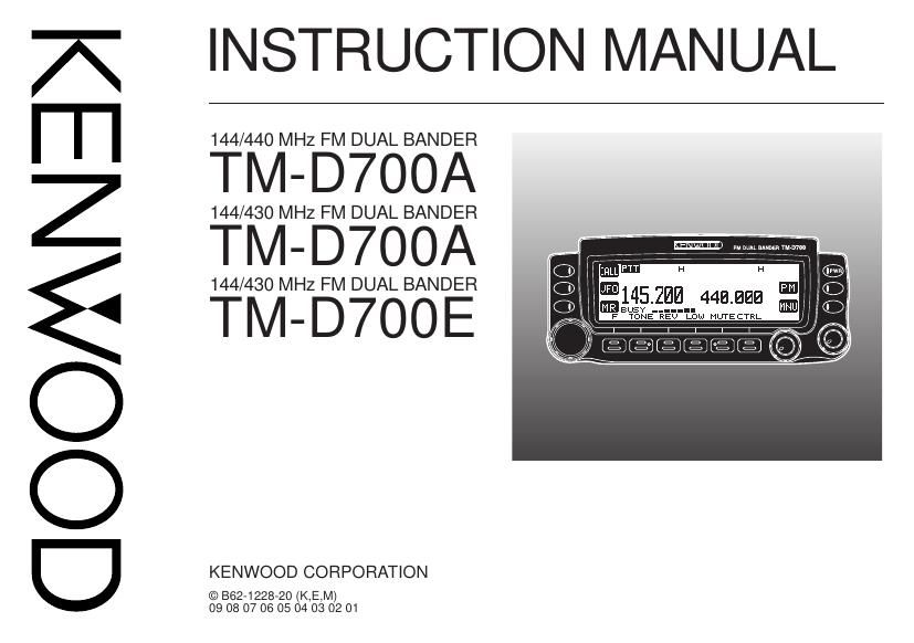
Kenwood TMD 700 E Owners Manual

This is the 99 pages manual for Kenwood TMD 700 E Owners Manual.
Read or download the pdf for free. If you want to contribute, please mail your pdfs to info@audioservicemanuals.com.

Page: 1 / 99
left right
Kenwood TMD 700 E Owners Manual

Extracted text from Kenwood TMD 700 E Owners Manual (Ocr-read)


Page 1

THANK YOU! We are grateful you decided to purchase this KENWOOD FM transceiver. KENWOOD always provides Amateur Radio products which surprise and excite serious hobbyists. This transceiver is no exception. This time KENWOOD presents a mobile with a built-in TNC to make data communications much more convenient than before. KENWOOD believes that this product will satisfy your requirements on both voice and data communications. MODELS COVERED BY THIS MANUAL The models listed below are covered by this manual. TM-D700A:144/440 MHz FM Dual Bander (U.S.A./ Canada) TM-D700E:144/430 MHz FM Dual Bander (Europe) TM-D700A:144/430 MHz FM Dual Bander (General market) FEATURES This transceiver has the following main features: ¥ Has a built-in TNC which conforms to the AX.25 protocol. With a portable computer, allows you to enjoy Packet operation quite easily. ¥ Includes a program for dealing with data formats supported by Automatic Packet/ Position Reporting System (APRS Ò).¥ Is capable of receiving packet data on one band while receiving audio on the other band. ¥ Enhanced Programmable Memory (PM) channels store virtually entire current operating environments for your quick recall. ¥ Contains a total of 200 memory channels to program frequencies and other various data. Allows each memory channel to be named using up to 8 alphanumeric and special ASCII characters. ¥ ÒVisual ScanÓ graphically and simultaneously shows the conditions of up to 181 frequency channels. ¥ Continuous Tone Coded Squelch System (CTCSS) or Digital Code Squelch (DCS) rejects unwanted calls from other stations. ¥ The separate front panel can be mounted in a convenient different place from the main unit. ¥ Equipped with an easy-to-read large LCD with alphanumeric display capability. ¥ Enhances the functions of an optional VC-H1 Interactive Visual Communicator designed for plug-and-play color slow-scan television (SSTV). ¥ Utilizes Sky Command System 2 designed to control a KENWOOD HF transceiver at a remote location (U.S.A./ Canada only).

Page 2

i PRECAUTIONS Please observe the following precautions to prevent fire, personal injury, and transceiver damage: ¥ When operating mobile, do not attempt to configure your transceiver while driving because it is simply too dangerous. ¥ Be aware of local laws pertaining to the use of headphones/headsets while driving on public roads. If in doubt, do not wear headphones while mobiling. ¥ Do not transmit with high output power for extended periods. The transceiver may overheat. ¥ Do not modify this transceiver unless instructed by this manual or by KENWOOD documentation. ¥ Do not expose the transceiver to long periods of direct sunlight nor place the transceiver close to heating appliances. ¥ Do not place the transceiver in excessively dusty areas, humid areas, wet areas, nor on unstable surfaces. ¥ If an abnormal odor or smoke is detected coming from the transceiver, turn OFF the power immediately. Contact a KENWOOD service station or your dealer. ¥ The transceiver is designed for a 13.8 V power source. Never use a 24 V battery to power the transceiver. NOTICES TO THE USER One or more of the following statements may be applicable: FCC WARNING This equipment generates or uses radio frequency energy. Changes or modifications to this equipment may cause harmful interference unless the modifications are expressly approved in the instruction manual. The user could lose the authority to operate this equipment if an unauthorized change or modification is made. INFORMATION TO THE DIGITAL DEVICE USER REQUIRED BY THE FCC This equipment has been tested and found to comply with the limits for a Class B digital device, pursuant to Part 15 of the FCC Rules. These limits are designed to provide reasonable protection against harmful interference in a residential installation. This equipment generates, uses and can generate radio frequency energy and, if not installed and used in accordance with the instructions, may cause harmful interference to radio communications. However, there is no guarantee that the interference will not occur in a particular installation. If this equipment does cause harmful interference to radio or television reception, which can be determined by turning the equipment off and on, the user is encouraged to try to correct the interference by one or more of the following measures: ¥ Reorient or relocate the receiving antenna. ¥ Increase the separation between the equipment and receiver. ¥ Connect the equipment to an outlet on a circuit different from that to which the receiver is connected. ¥ Consult the dealer for technical assistance. When condensation occurs inside the transceiver: Condensation may occur inside the transceiver in such a case where the room is warmed using a heater on cold days or where the transceiver is quickly moved from a cold room to a warm room. When condensation occurs, the microcomputer and/or the transmit/receive circuits may become unstable, resulting in transceiver malfunction. If this happens, turn OFF the transceiver and just wait for a while. When the condensed droplets disappear, the transceiver will function normally.

Page 58

53 9 n Using Program Scan 1Select the appropriate band. 2Press [VFO] . 3Select a frequency equal to or between the programmed scan limits. 4Press [VFO] (1 s). ¥ Scan starts at the frequency currently displayed. ¥ The 1 MHz decimal blinks while scanning is in progress. ¥ To reverse the scan direction, turn the Tuning control clockwise (upward scan) or counterclockwise (downward scan). You can also press Mic [UP]/ [DWN]. 5To quit Program Scan, press [VFO] again. Note: u If the step size of the current VFO frequency differs from that of the programmed frequencies, VFO scan starts instead of Program Scan. u If the step size differs between the lower limit and the upper limit, VFO scan starts instead of Program Scan. u If the current VFO frequency is within more than one programmed scan range, the range stored in the smallest channel number is used. MHz SCAN MHz Scan monitors a 1 MHz segment of the band, using the current frequency step size. The current 1 MHz digit determines the limits of the scan. For example, if the current frequency is 145.400 MHz, then the scan range would be from 145.000 MHz to 145.995 MHz. The exact upper limit depends on the current frequency step size. 1Select the desired band. 2Press [VFO] to select VFO mode. 3Select a frequency within the desired 1 MHz segment. 4Press [MHz] (Tuning control) (1 s). ¥ Scan starts at the frequency currently displayed. ¥ The 1 MHz decimal blinks while scanning is in progress. ¥ To reverse the scan direction, turn the Tuning control clockwise (upward scan) or counterclockwise (downward scan). You can also press Mic [UP]/ [DWN]. 5To quit MHz Scan, press [MHz] again. 1 s

Page 73

68 14 S-METER SQUELCH S-meter Squelch causes the squelch to open only when a signal with the same or greater strength than the S- meter setting is received. This function relieves you from constantly resetting the squelch when receiving weak stations that you have no interest in. 1Select the desired band. 2Press [MNU] to enter Menu mode. 3Select 1Ð3Ð2 (S-METER SQUELCH), then press [OK]. 4Press [ c cc c c]/ [ d dd d d] to switch the function ON (or OFF). 5Press [OK] to complete the setting. 6Press [MNU] to exit Menu mode. ¥ The S-meter setting segments appear. 7To select the desired S-meter setting, turn the left (band A) or right (band B) SQL control depending on which band you selected. n Squelch Hang Time When using S-meter Squelch, you may want to adjust the time interval between when the received signals drop and when the squelch closes. Access Menu 1Ð3Ð3 (SQUELCH HANG TIME) and select from OFF (default), 125, 250, and 500 msec.