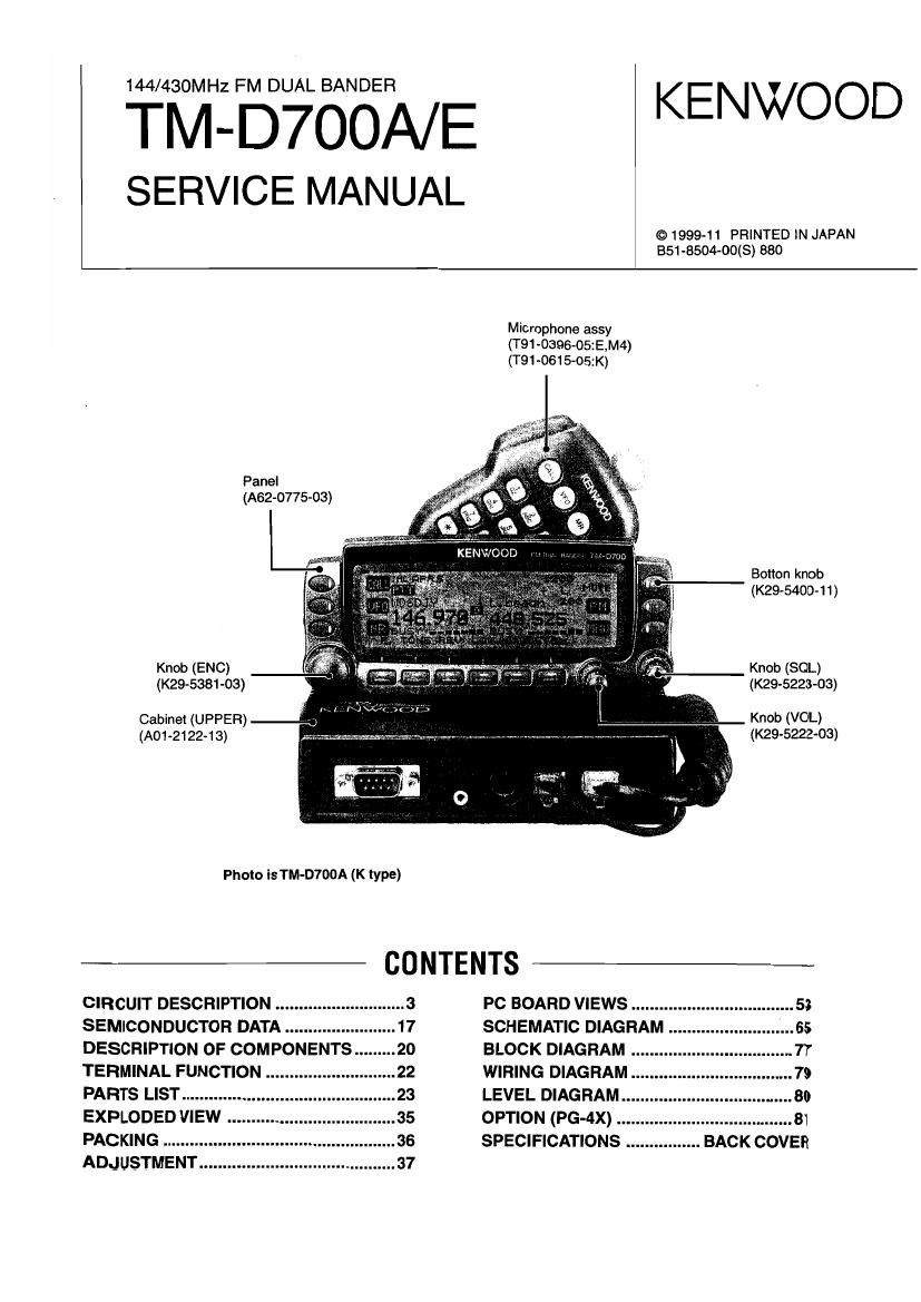
Kenwood TMD 700 A Service Manual

This is the 68 pages manual for Kenwood TMD 700 A Service Manual.
Read or download the pdf for free. If you want to contribute, please mail your pdfs to info@audioservicemanuals.com.

Page: 1 / 68
left right
Kenwood TMD 700 A Service Manual

Extracted text from Kenwood TMD 700 A Service Manual (Ocr-read)


Page 2

TM-D7OOA/ E

CIRCUIT DESCRIPTION

Outline

This device is a dual-band 144/430MHz FM car transceiver

planned and designed for amateur radio communications and
has the lollowing features

1.

10.

11.

Has a built-in TNC which conforms to the AX.25 protocol.
With a portable computer, allows you to enjoy Packet
operation quite easily.

includes a program for dealing with data formats supported
by Automatic Packet/ Position Reporting System (APRSG).
ls capable of receiving packet data on one band while
receiving audio on another band.

Enhanced Programmable Memory (PM) channels store
virtually entire current operating environments for your
quick recall.

Contains a total 01 200 memory channels to program
frequencies and other various data. Allows each memory
channel to be named using up to 8 alphanumeric and
special ASCII characters.

"Visual Scan graphically and simultaneously shows the
conditions of up to 181 frequency channels.

Continuous Tone Coded Squelch System (CTCSS) or
Digital Code Squelch (DCS) reiects unwanted calls from
other stations.

The separate iront panel can be mounted in a convenient
different place trom the main unit.

Equipped with an easy-to-read large LCD with
alphanumeric display capability.

Enhances the functions of an optional VC-H1 interactive
Visual Communicator designed for plug-and-play color
slow-scan television (SSTV).

Utilizes Sky Command System [I designed to control a
KENWOOD HF transceiver at a remote location (U.S.AJ
Canada only).

List of Destinations

Modal Guarantee frequency range (MHz) Output Power (W)
1 44 430 1 44 430
TM-D700A K 144~148 438450 50 85
M4 144-146 430~440 J 25 25
TM-D700El E 144~146 430-440 J 50 35

K: USA/Canada M4: Taiwan E: Europe

Accessories
Name Parts number Remarks Destination
K E M4
Modular cable E30-3391-05 3m 1 1 1
Panel bracket £10663 1 1 1
J29-0664-13 1 1 1
Bracket J29-0628-23 1 1 1
Microphone T91-0396-o5 1 1
T91-0615-05 DTMF BACK LIT 1
DC cord E30~2111-15 1 1 1
Fuse F51-0017-05 15A 1 1 1
Mic Hook J19-1526-04 1
862-1228-00 English 1 1 1
862-1232-00 French 1 1
362-1231-00 Spanish 1 1
Instruction manual B62o1230~00 German 1
362-1233-00 Dutch 1
362-1273-00 English APRS 1 1 1
562-1234-00 Chinese 1
B62»1229-00 Italian 1
Warranty card BAG-04694 CI 1
846-0337-03 1
Cable E30-3400~05 02.5mm GPS jack 1 1 1
Screw set N99-0331-05 For the body 1 1
Screw set N99-0382-05 Fertile body and MIC look 1
§crew set N99-2014-05 Forthepanei bracket 1 1 1
Foot J02-0488-04 For protect from 4 4 4
scratch on a desk
Pamphlet l 859-1684-00 1

Units for Each Model and Destination

Model TX-RX UNlT LCD ASSY

K x57-5aeo-1 1 SSS-082905
TM'D700A M4 x57-seso-21
TM-D700E E X57-5862-71

Page 37

TM-D7OOA/ E

ADJUSTMENT

Measuring Equipment for Adlustment

1. Digital voltmeter (D.V.M)
input impedance: High

2. RF valve voltmeter (HF V.M)
Input impedance: 1M 0 or more. 2 pF or less
Voltage range: Full scale = 10mV to 300V
Measurable frequency range: up to 450MHz

3. Frequency counter (1. counter)
Input sensitivity: About 50mV
Measurable frequency: 450MHz or more

4. DC power supply
Voltage: Variable in the range 10 to 17V
Current: 13A or more

5. Power meter
Measurement power: 60W, 30W, 10W
impedance: 50 Q
Measurable frequency: 450MHz

6. AF valve voltmeter (AF V.M)
Input impedance: 1M 0 or more
Voltage range: Full scale = 1mV to 30 V
Measurable frequency range: 50Hz to 10kHz

7. AF generator (AG)
Output frequency: 100Hz to 10kHz
Output voltage: 0.5mV to 1V

8. Line detector
Measurable frequency: 450MHz

9. Spectrum analyzer
Measurable frequency: 450MHz

1 0. Directional coupler
1 1. Oscilloscope
High sensitivity with horizontal input terminal

1 2. Standard signal generator (386)
The standard signal generator must be able to generate
the tGHz band frequencies and vary the amplitude and
lrequency.
Output: -133dBm to greater than <13dBm

13. Dummy load (for AF)
an. about SW

14. Noise generator
The noise generator must be able to generate noise
similar to ignition noise containing high-frequency
components of 450MHz or more.

15.5weep generator
The sweep generator must be able to sweep the 144
and 430MHz bands.

1 6.Tracklng generator
1 7. Adjustment iig

Preparation

0 Set the controls and switches to the positions listed
below unless otherwise specified.

VOL control Fully counterclockwise
SOL control Fully counterclockwise
POWER switch OFF

(For fixed stations) OFF

DC power supply POWER switch

UP - - own
cs
(DCBV2100rnA max.) NC
E MIC
PTT ME

Microphone socket
(as viewed from the front of the set)

C Use an insulated rod, such as a plastic rod, for
adjustment (especially for trimmers, coils, etc).

0 To protect the signal generator, never connect the
microphone to the microphone socket when the
receiver section is adjusted.

0 Before the power cord is connected, make sure the
power switch is off.

0 Without specification of SSG. standard modulation is
applied (MOD : 1kHz, DEV : :SkHz, AF output :
0.63V/ an)

0 See the instruction manual for transmit and receive
operations.

37