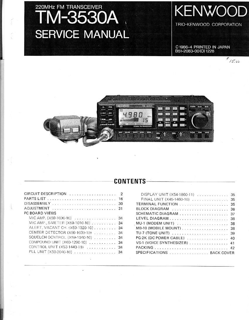
Kenwood TM 3530 A Service Manual

This is the 57 pages manual for Kenwood TM 3530 A Service Manual.
Read or download the pdf for free. If you want to contribute, please mail your pdfs to info@audioservicemanuals.com.

Page: 1 / 57
left right
Kenwood TM 3530 A Service Manual

Extracted text from Kenwood TM 3530 A Service Manual (Ocr-read)


Page 2

W

CIRCUIT DESCRIPTION

VTMGSSOA

FINAL UNIT

x45-i46040

ILL UNIT

>_ X50-2040-10

contact UNIT

X53 1440711

DISPLAY UNIT

X54-1860-1l

COMPOUND UNIT

X6071 29010

Table 'l TM-3530A PC board chart

RX SECTION

Signals from the antenna are applied to the FINAL unit
(X601290-10) transmit receive switching circuit, D2 and
D4. In receive, diodes I72 and D4 are reverse biased forcing
the incoming receive signal down thru L3 to the RA the»
nerve Antenna) terminal. There the incoming receive signal
is then coupled to the COMPOUND Unit (XSO-lZQO-lO)
The signal is filtered by low pass filter and amplified by
Di the first RF amplifier, a GaAs FLT 33K1?9(S).The
arriolrlied RF signal is then mixed with the LR (Receiver
I.nr.al Oscrllalor) Signal in the first mixer 02. 3$K74lLl to
obtain the First IF frequency of 20.935MHZ. This IF signal
is filtered by l-lelicai Resonator, L4, and a two stage MCF
IMUIlUIIll'liC Crystal Filter), L8, which combine to provrde
excellent two-signal characteristics and sensitivity,

the liirst ll Signal frnrn lne MCF is then arnplilicd by the
First lF amplifier 03 ZSCZESBBW) and applied to the Hvl
iF Arriplifier/MixcrI'Dctectoi, ICZ : TA7761P. This signal
lC mixes the [F signal with the 20.48MHz 2nd Local Oscil-
lator signal (Li/l) to obtain the. 2nd lF frequency of
455kHz, then amplifies, routes the signal thru external
filter L16, and finalty convenes it into the received audio
signal With the internal quadrature detector. The 7nd Local
Oscillator signal from Ll4 and IC2 is also used by the PLL
unit as a Reference signal.

The detected audio output from lC? is applied to the
SOUELCH CONTROL (X59v1040-10l, and to the ne-
emphasis circuit H56 and C99. The (deemphasized) audio
is amplified by Audio preamplifier 09 ' 28C2458W) and
then applied thru the AF GAIN control to the Audio Amp-
lifier ICi uPClZAi H which drives the speaker.

The noise component of the detected audio is filtered by a
band-pass filter, in order to obtain a frequency of appro-
ximately BOkHz (which is well outsrde the normal vorce
bandwidth) and then amplified by the noise amplifiers
contained inside ICZ. This amphfred noise IS rectified by
diodes 06 and D5 and applied to 01 of the Squelch Switch.
01 is used to control the conduction of OZ. which controls
AF Preamp (.19.

A center-slop tuning circuit is provided to ensure that the
incoming signal is actually on frequency before the squelch
is opened. A portion of the 465kHz IF signal is coupled
lhrir the secondary of L17 and applied to CENi Hi STOP
unit (X59~103(l~10) where. Cerarnrr: l,)iscrrminator Liz, and
Window comparator lCi ' NJM4558M an;- used to deter-
mine if the incorriirig Slglldl is actually the channel centers
When the detected srnnal applied in the window compara-
tor reaches a predetermined level, ()5 of the Sqrrelch Switch
wdl be turned OFF or ON. The Squolch Switch determines
if there is Hl ifllIUlillllg signal at the same time, If the iri-
cnmrnn siqnal is at the proper level, and on lreqrienry the
squelch will open and the C.TUNf" indicator in the LCD
display will turn ON. This indicator is Controlled by lCQ.
the main microprocessor on the CONTROL unit
(XSB- l440- l i), thru inputs- supplied from the COM-
POUND unit via the 80 line. During Open Channel Scarr-
ninri of the DCL system 03, CI, and Q9 of the Squeltrh
Switch are controlled by the. main mirrnprnressnr via the
808 line. During DCL operations open channel Search thre~
shold levels are controlled try VH3 of the Compound ass'y.
Transistor (16 of the Squelch Switch, is used to prevent the
Center Stop Circuit from activating during Open Channel
Scan Operation.

Note I :

The Center Stop circuit is not activated during Open Chan-
nel Scan,

Window comparator frequency

,Jf' bandwidth.

/ '

\ Frequency of desired One" Channel
Channels

Interference such as lMDfrom strong adjacent channels
makes the use of the Center Stop function erratic during
Open channel scan.

Fig. 1
Audio Preamplifier 09 is controlled by Oi of the Alert,
Vacant CH. unit thQ-iOZO-ltll during Alert, code Squeich
and Open Channel operations.

Page 8

TM-3530A

CIRCUIT DESCRIPTION

CONTROL UN IT (X53-1440-11I

The CONTFOL urn: uses two Microprozessors. the Main
Microprocessor 1C2 TMP47C46N-9044 and Auxilliary
M crcpmcessor lC3 : [.LPD75008I'IC0b6, Bmh utilize 4 IJII
architecture anti have 4K By as oi ROM available,

Mair" M cropr sor com'ols; frequency, offset, tone,
memory lrmuermy, lauy, swiZFI encoder, lreqncncy dis
plan, DCL system and the Arrxillwy Microprocessor lhr'.
Auxrlliary lxfiiurcprocessor Controls, the voice synthesmer,
ClSDIaV,C)HIrldlU rnurrmry for talenhnne nurrbur r'unc
lions, tone frequencies, audio oscillator. and digiial signal
conversron and analysis pro 19 for DCL system.

The Vfim Mirzrupruccssor utilv 95 a serial :illelIdci: bu: l0
izry mm or. A CMOS 3mm HAM, 1C6
'i I:I)(I17AD'I wirh .1 *apar: y mi iK x 4 bin. is used lrnr
-3><:ema rrwmow, fliJldgfl 9 noPrarnr pruurmnrrrud dam

u AL!

-ry erqm-e'rrjé-S and telephgrc number «lam la
«7 data hnllur who. uxdrungi data LT .
me Mam rim: Aux' lia'y prcrpsswra IJILHWV dLILIl'CL»;
mg i; l ormai h'y HES TC4OH374P with read and Write
fipeldiIUIS being hard Ed by 1:. Data Bus.

sir H as

,/'

I. CH
23/6
CS / PRIO
KOI"
I);
+

%
9
IV!
\
I

\

FIEV C/

SW RETURN
7
g
13
, I
Z.
.
l 0\

/ /

RC2 R4! H40
\, fiv-,

SW SCAN OUTPUT (ACTIVE LOW)

Fig. 9 Diode matrix

Switch Section

With a few euepmns most swrrch rniiuls rm rhe iron!
panel are arranged in a diode matrix. The Main Mimopm
cessor reads the inputs via a keyboard slams scan system,
lhrs system dmernnnes which key, ii any, has been de-
pressed,

The diode matrix is iilustraled in Fig. 9

The PHONE swrtch, TONE switch, PTT switch, UP switch
and DOWN swrrch all supply inputs directly lo the Main
Microprocessor

Keyboard section

I'LL]. Il illuslruius the keyboard SQCUOIT Cirrtuit rliagrarnfnc
keyboard receive; smn pulses lrorn (hr: Main MICVCITNAP
Lessor ports P10 thrrr PM [he nrrerrr keyboard slams is
IRLLHHUU via pom R70 1hrLr R73. I'LliIrllD mitiglms ni PlO
thrn Ill}, arr»: CillillIrIILiI my pull R90. Keyboard SIHTllS is,
stunned when R90 I9 nrillnrl i4) Imm loqir; low by 03
l) I A1 MVP,

Display section
lliq. il SHUW> Uri. layout til the 1 (2|)

The LCD driver (Keyboard usb'y) r, currirorlncl m l} daia
lrrws and 4 Control lines on d parallel bus Sybivlll by the
Mam and Auxilliury r'nicrnpromqsnrq.

Data transrer is irmsilm only when the CS liru-e i9 l nw anrl
In wrijuclion with The, leading edge ol llru WE pulse. Th9
I)( 1 and C03 LED': am In by Iii/Ill, HUI} LJ/I 'Illll OE Wl'riur
arc. mmmlluu by the Main Mrcr'rrpror

Efll

Page 53

" TU-7 (TONE)

TU-7 OUTSIDE VIEW TU-7 PARTS LIST
Part No. wit; Descnption Q'Ty Ref. No.
TU-7 (GENERAL)
8508045-00 N Instruction manual 1
531,350.05 N CabIP. assembly 1
613082604 N Cushion 1
6310826 04 Foam spacer 1
H01-4679-03 N Cartcw (Inside) 1
H25-0029'04 Protective bag 2
20791.04 N Hex. head boss 1
TU-7 PC BOARD VIEW _
lX52-1330-20) Componem side view 11351260441 Bindingsmw 2
{ X52-1330-20 N Tone unil l
TONE UNIT (X52-1330-201
CEOACW1A1OOM Electro 10;; 10V 1 C4
CK73EBIH473K Chip cap. 0,0471: 1 C2
. C91 075705 CeramlC 0.001;; 1 C3
13406021 -05 Mlni-connecmr 7P 1
L78-0018»05 N Ceramic oscillalor 1 X1
1 1312-3445 05 Tlirnming pol. 471d? 1 VR'I
M888306 N IC 1 [C2
S7116A N IC 1 1C1
TU-7 INSTALLATION AND TONE FREQUENCY

SETTING PROCEDURE

Available CTSS {one frequenmes

\ V H2 H2 _____ Hz

57,0 7 7 114.8 192.8
71.9 118.8 203.5
74.4 123.0 210.7
77.0 127.3 218,1
79,7 131.8 " 225,7
8? 5 136.5 233.6
85.4 141.3 1 241.8
88.5 146.2 250.3
91 5 151 4

94,8 156 7

97.4 162.2

100.0 157.9

103 5 173.8

107 2 179.9

110.9 186.2

Rele1 to 11112 111s1ructinr1 manual DIKJVldBd WW1 (he Iranscewev.

39