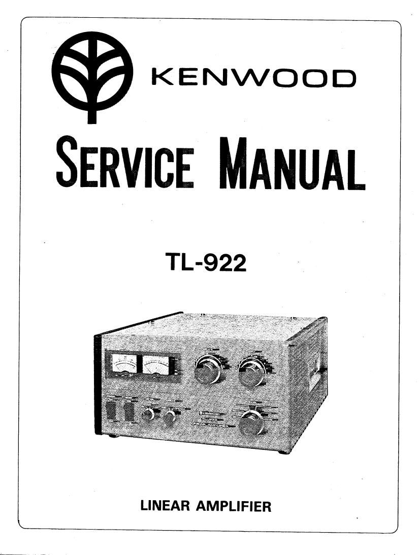
Kenwood TL 922 Service Manual

This is the 31 pages manual for Kenwood TL 922 Service Manual.
Read or download the pdf for free. If you want to contribute, please mail your pdfs to info@audioservicemanuals.com.

Page: 1 / 31
left right
Kenwood TL 922 Service Manual

Extracted text from Kenwood TL 922 Service Manual (Ocr-read)


Page 1

KENWOOD

SERVICE MANUAL

TL-922

LINEAR AMPLIFIER

Page 2

CONTENTS

SECTION 1 . IMPORTANT NOTICE ..................... . ........................................ 3
SECTION 2.1 TECHNICAL SPECIFICATIONS ............................................... 3
SECTION 2.2 TUBE SPECIFICATIONS. 4
SECTION 3. FEATURES. 4
SECTION 4. CIRCUIT DESCRIPTION .. 5
SECTION 5. VIEWS
External View ........................................................................ 8
Intemal View ........................................................................... 9
SECTION 6. PRINTED CIRCUIT BOARDS
Rectifier Uriit (X43-1280-10) . . 1 0
Meter Unit(X54-1300-10).... 10
SECTION 7. PARTS LIST .............................................................................. 1 1
SECTION 8. PACKING .................................................................................. 13
SECTION 9. DISASSEMBLV AND ADJUSTMENT NOTES ............................ 14
SECTION 10. DISASSEMBLY ....................................................................... 1 5
SECTION 1 1. LINE VOLTAGE CHANGE... .. 20
SECTION 12. TROUBLESHOOTING . 21
SECTION 13. ADJUSTMENTS ............ 22
SECTION 14. REFERENCE DATA [EXAMPLE]. ............................................... 24
. SECTION 15. SCHEMATIC DIAGRAM [W Type]...: ....................................... 27
SCHEMATIC DIAGRAM [K Type] ........................ Attached sheet
ILLUSTRATIONS:
Fig. 1 Linear Power Amplifier and Mode Switching Circuit .......................... 5
Fig. 2 Fan Motor Delay Stop Circuit ........... . 6
Fig. 3 Meter Drive Circuit 5
Fig. 4 Transformer Thermal Protection Circuit .. 7
Fig. 5 Chassis and Front Panel. .. 15

Fig. 6 Subpanel ...................... .. 16
Fig. 7 Rear Panel ................. .. 16
Fig. 8 Electrolytic Assembly. 17
Fig. 9 Relay and Meter Mountings . .. 17

Fig. 10 Disassembly Power Transformer ............ .. 18
Fig. 11 Dieassembly Filament Transformer ........ .. 18
Fig. 1 2a Disassembly Plate Variable Capacitor ..... .. 19
Fig. 12b Output Coupling Capacitor
Fig. 13 Rectilying Unit .................

Fig. 14a Input Voltage Terminal Boards [K TypeL
Fig. 14b Input Voltage Terminal Boards [W Type].
Fig. 15 Equipment Connection.

Fig. 16 Coil Locations .....
VIEWS:
Tube Basing ..... 3
Front and Rear. 8
Inside Top and Bottom ..................................................................................... 9
Printed circuit Boards
Rectifier Unit ................................................................................................. 10
Meter Unit... .. 10

Packing ......