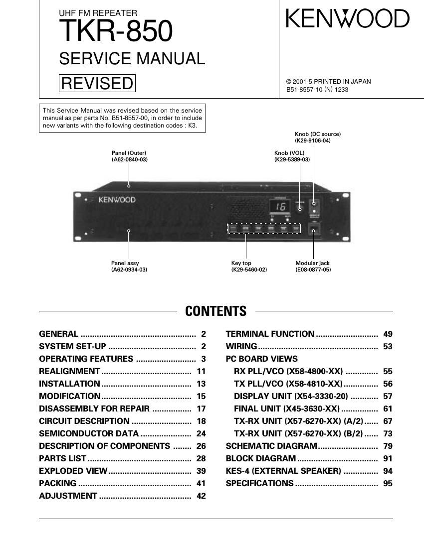
Kenwood TKR 850 Service Manual

This is the 71 pages manual for Kenwood TKR 850 Service Manual.
Read or download the pdf for free. If you want to contribute, please mail your pdfs to info@audioservicemanuals.com.

Page: 1 / 71
left right
Kenwood TKR 850 Service Manual

Extracted text from Kenwood TKR 850 Service Manual (Ocr-read)


Page 1

2 TKR-850 GENERAL / SYSTEM SET-UP INTRODUCTION SCOPE OF THIS MANUAL This manual is intended for use by experienced techni- cians familiar with similar types of commercial grade com- munications equipment. It contains all required service in- formation for the equipment and is current as of this publica- tion date. Changes which may occur after publication are covered by either Service Bulletins or Manual Revisions, which are issued as required. ORDERING REPLACEMENT PARTS When ordering replacement parts or equipment informa- tion, the full part identification number should be included. This applies to all parts : components, kits, and chassis. If the part number is not known, include the chassis or kit number of which it is a part and a sufficient description of the required component, for proper identification. PERSONNEL SAFETY The following precautions are recommended for person- nel safety : - DO NOT transmit until all RF connectors are secure and any open connectors are properly terminated. - SHUT OFF this equipment when near electrical blasting caps or while in an explosive atmosphere. - This equipment should be serviced by only qualified tech- nicians. SERVICE This radio is designed for easy servicing. Refer to the schematic diagrams, printed circuit board views, and align- ment procedures contained in this manual. Merchandise received Choose the type of transceiver Installation in the optional space Frequency range (MHz) TX/RX 450~480 TX/RX 480~512 TX/RX 400~430 TX/RX 440~470RF power 40W 40W 40W 40WType K K2 K3 E See page 11. A personal computer (IBM PC or compatible), programming interface (KPG-46), and programming software (KPG-66D) are required for programming. YES NO DC power supply or duplexer? KES-4 installation YES NO External speaker? Repeater programming & setup Delivery SYSTEM SET-UP

Page 2

3 TKR-850 OPERATING FEATURES 1. Controls and Functions 1-1. Front Panel 1 Speaker 2 CH/STATUS Display Two, 7-segment digits display the channel number or sta- tus. 3 VOLUME control Rotate to adjust the volume. 4 DC source ON/OFF switch 5 DC source indicator Lights green when DC source is applied from the DC 13.6V jack (DC 13.2V jack on E type versions). Lights red when DC source is applied from the BACKUP battery ter- minal. 6 MIC jack Connect a microphone to this 8-pin modular jack. 1 9 8 7 6 3 4 5 2 1 TX OUT jack Connect a TX antenna or a duplexer to this receptacle. 2 CONTROL I/O jack Connect an external programming device or repeater controller to this DB-25 interface. 3 FUSE Insert 15 A blade fuses into these fuse holders. 4 RX IN jack Connect a RX antenna or a duplexer to this BNC recep- tacle. 7 Programmable Function keys Press these keys to activate their programmable func- tions. PF1 key (left side) Default : None (No function) PF2 key Default : Repeat disable/enable PF3 key Default : TX disable/enable PF4 key Default : Take over PF5 key Default : Monitor on/off PF6 key (right side) Default : Channel up 8 BUSY indicator Lights green while a signal is being received. 9 TX indicator Lights red while transmitting. 1 7 6 5 2 8 3 4 9 1-2. Rear Panel 5 DC 13.6V (K type) / DC 13.2V (E type) jack Connect a 13.6 V (K type) or 13.2 V (E type) DC power supply to this jack. 6 BACKUP battery terminal 7 TEST/SPKR jack Test input/output jack. Connect an external speaker to this jack. 8 Cooling fan 9 Optional space For external DC power supply, or duplexer, etc.

Page 22

23 TKR-850 5-6. DSP The DSP circuit filters transmit/receive audio signal and encode/decodes signaling (QT, DQT). This circuit consists of IC618, IC612, IC613, IC614, IC603, IC606, IC608, IC610, IC616, and IC619. The receive signal DET is converted from analog to digital by IC614 with a sampling frequency of 16.128kHz. The digi- tized audio signal is sent to DSP IC618 to process the signal- ing signal and audio signal. The processed digital audio sig- nal is fed to CODEC IC613, converted from digital to analog, and the analog signal is output from pin 16 (AOUTR). Then, the audio signal is amplified by IC619 (B/2), passes through the IC619 (A/2) low-pass filter, and goes to an electronic vol- ume IC615. The transmit audio signal coming from IC605 is amplified by IC610, fed to pin 3 (AINL) of CODEC IC614, and con- verted from analog to digital at a sampling frequency of 16.128kHz. The digitized transmit audio signal is AGC-pro- cessed, pre-emphasized and filtered at 300Hz to 3kHz by DSP IC618, and the resulting signal is fed back to CODEC IC614, and converted from digital to analog, and the analog signal is output from pin 15 (AOUTL). The transmit signal from AOUTL is amplified by IC616 (B/2), passes through the IC616 (A/2) low-pass filter, and goes to the IC611 (A/2) sum- ming amplifier. IC613 is a counter IC and the clock required for the CODEC and DSP is generated by dividing the 16.515MHz clock signal produced by DSP IC618. IC603 and IC606 are interface IC between the CPU oper- ated at 5.0V and the DSP operated at 3.3V. 5-7. Base-Band Circuit The base-band circuit switches between the modulation signal to the transmitter circuit, and remote audio and ad- justs their levels. This circuit consists of IC605, IC607, IC611, IC615, and IC617. Modulation inputs include local microphone input, low- speed data (LSD), high-speed data (HSD), external audio in- put (TA), and external data input (TD), and demodulation out- puts include receive audio output (RA), and receive data out- put (RD). The multiplexer (IC605) changes signals, the electronic volume (IC615) adjusts the level, and the operational ampli- fier (IC607, IC611, IC617) amplifiers and sums signals. 5-8. RS-232C Circuit The RS-232C circuit connects the RS-232C serial port of a personal computer directly to this model to perform FPU operation. The FPU operation can also be performed by con- necting a programming cable (KPG-46) to the local micro- phone on the front panel. But, if the D-sub connector on the rear panel is used, the programming cable is not required. The 232C driver IC (IC620) changes the TTL-232C level. The firmware can only be rewritten with the local microphone on the front panel. 5-9. Power Supply Circuit The power supply circuit generates power to operate the CPU, DSP, flash ROM, bi-directional buffer, and base-band circuit. This circuit consists of IC624, IC625, IC626, IC627, IC628, and IC630. 6. DC Power Supply Circuit 6-1. DC Source Switching Relay Circuit 1. The final unit contains a relay (K1) for switching between the Main DC and Backup Battery. If an external power source is connected to the Main DC terminal, the Backup terminal is isolated by the relay. If the Main DC turns OFF due to power failure, it is switched to the Backup terminal by the relay. The CPU monitors which is used, Main DC or Backup Battery. 2. Trickle charge circuit If both Main DC and Backup Battery are connected, trickle charging of 0.5 A max. can be performed from the Main DC power supply to the Battery. (The default is OFF. See the Modification section for in- formation on the modification method.) The battery is charged from the Main DC with D8, D9 and R61. If it exceeds 0.5 A, the charging circuit is turned OFF by D9. 6-2. SB Switching Relay Circuit 1. SB (Switched +B) is supplied through the relay (K1) in the TX-RX unit A/2. When S507 (DC source switch) in the display unit is turned ON, the relay (K1) is turned ON to output SB. 2. If +B exceeds 18V, the relay is forcibly turned OFF by D12 and Q25 to interrupt the power and protect the main unit. D8 D9 R61 Land Main DC Backup battery 120mA+B K1 (Relay) Final unit (A/2) TX-RX unit (A/2) TX-RX unit (B/2)R54 IC604 CPUBUP16 Q601 +B R165 R166 D12 K1 Q24 Q25 SB Land (PSW) Display unit (Front panel) S507 Fig. 9 DC source switching relay circuit Fig. 10 SB switching relay circuit CIRCUIT DESCRIPTION

Page 35

TKR-850 PARTS LIST 36 Ref. No. Address Parts No. Description Ref. No. Address Parts No. Description New Desti- parts nation New Desti- parts nation R788 RK73GB1J473J CHIP R 47K J 1/16W R789 RK73GB1J102J CHIP R 1.0K J 1/16W R790 RK73GB1J473J CHIP R 47K J 1/16W R791 RK73GB1J102J CHIP R 1.0K J 1/16W R792 RK73GB1J473J CHIP R 47K J 1/16W R793 RK73GB1J102J CHIP R 1.0K J 1/16W R794 RK73GB1J473J CHIP R 47K J 1/16W R795 RK73GB1J102J CHIP R 1.0K J 1/16W R796 RK73GB1J473J CHIP R 47K J 1/16W R797 RK73GB1J102J CHIP R 1.0K J 1/16W R798 RK73GB1J473J CHIP R 47K J 1/16W R799 RK73GB1J102J CHIP R 1.0K J 1/16W R800 RK73GB1J473J CHIP R 47K J 1/16W R801 RK73GB1J102J CHIP R 1.0K J 1/16W R802 RK73FB2A2R2J CHIP R 2.2 J 1/10W R803 RK73GB1J473J CHIP R 47K J 1/16W R804 RK73GB1J102J CHIP R 1.0K J 1/16W R805 RK73GB1J473J CHIP R 47K J 1/16W R806 RK73GB1J102J CHIP R 1.0K J 1/16W R807 RK73GB1J473J CHIP R 47K J 1/16W R808 RK73GB1J102J CHIP R 1.0K J 1/16W R809 RK73GB1J473J CHIP R 47K J 1/16W R810 RK73GB1J102J CHIP R 1.0K J 1/16W R811 RK73GB1J473J CHIP R 47K J 1/16W R812 RK73GB1J223J CHIP R 22K J 1/16W R813,814 RK73GB1J473J CHIP R 47K J 1/16W R815 RK73GB1J104J CHIP R 100K J 1/16W K1 S76-0401-05 RELAY D1-4 DAN235K DIODE D5 MA742 DIODE D7 1SS355 DIODE D8 DAN235K DIODE D9 HSM88AS DIODE D11 02DZ5.1(Y) ZENER DIODE D12 02DZ18(X,Y) ZENER DIODE D13 MA742 DIODE K3 D600 DA204U DIODE D601 MA2S111 DIODE D606-625 DA204U DIODE D626 MINISMDE190 VARISTOR D627,628 1SS355 DIODE D629 DA204U DIODE IC1,2 NJM4558E MOS IC IC3 NJM78L05UA BI-POLAR IC IC4 NJM7808FA BI-POLAR IC IC5 AN8009M MOS IC IC6 M62354GP MOS IC IC7 BU4094BCF MOS IC IC9-œ½TK14489V BI-POLAR IC IC10 TA7808F ANALOG IC IC11 NJM78L05UA BI-POLAR IC IC600 AT2408N10SI2.5 ROM IC IC601 RH5VL42C MOS IC IC602 BU4094BCFV MOS IC IC603 TC74LVX4245FS MOS IC IC604-œ½30622M4-113GP MPU IC605 BU4053BCF MOS IC IC606 TC74LVX4245FS MOS ICIC607 NJM4558E MOS IC IC608 TA75S01F MOS IC IC609 AT29C020-90TI ROM IC IC610 TA75S01F MOS IC IC611 NJM4558E MOS IC IC612 TC7S04FU MOS IC IC613 TC74VHC4040FT MOS IC IC614 AK4550VT MOS IC IC615 M62364FP MOS IC IC616,617 NJM4558E MOS IC IC618 320VC5402PGE MPU IC619 TC75W51FU MOS IC IC620-œ½ADM202EARN MOS IC IC621 TC7S00FU MOS IC IC622 TC7S66FU MOS IC IC623 BU4094BCFV MOS IC IC624 XC62FP1802P MOS IC IC625,626 XC62FP3302P MOS IC IC627,628 TA78L05F MOS IC IC629 3B LA4422 BI-POLAR IC IC630 TA78L05F MOS IC Q1,2 2SC3357 TRANSISTOR Q3 2SC3356(R24) TRANSISTOR Q4 DTC144EUA DIGITAL TRANSISTOR Q5 DTA144EUA DIGITAL TRANSISTOR Q6 DTC144EUA DIGITAL TRANSISTOR Q7 2SC4617(S) TRANSISTOR Q8,9 2SC3356 TRANSISTOR Q10 2SC3357 TRANSISTOR Q11 2SC3356(R24) TRANSISTOR Q12-15 2SC4116(GR) TRANSISTOR Q16 2SB1132(Q,R) TRANSISTOR Q17 DTC114EUA DIGITAL TRANSISTOR Q18 2SB1386(R) TRANSISTOR Q19,20 DTC114EUA DIGITAL TRANSISTOR Q23 DTC114EUA DIGITAL TRANSISTOR Q24 DTD114EK DIGITAL TRANSISTOR Q25 DTC114EUA DIGITAL TRANSISTOR K,K2,E Q25,26 DTC114EUA DIGITAL TRANSISTOR K3 Q600 2SK1824 FET Q601 DTC114EUA DIGITAL TRANSISTOR Q602 2SK1824 FET Q603 DTC114EUA DIGITAL TRANSISTOR Q604 2SK1824 FET Q605 DTC114EUA DIGITAL TRANSISTOR Q606 DTC363EK DIGITAL TRANSISTOR Q609 DTC114EUA DIGITAL TRANSISTOR Q610 2SJ506(S) FET Q611 DTC114EUA DIGITAL TRANSISTOR TH1 157-503-53006 THERMISTOR A1 W02-1939-05 DBM C304,305 CK73GB1H102K CHIP C 1000PF K C306 CK73GB1H103K CHIP C 0.010UF K C307 CK73GB1H471K CHIP C 470PF K C308-310 CK73FB1E104K CHIP C 0.10UF K C311 C92-0001-05 CHIP C 0.1UF 35WV RX PLL/VCO (X58-4800-XX) -10 : K,E -11 : K2 -12 : K3 TX-RX UNIT (X57-6270-XX) RX PLL/VCO (X58-4800-XX)