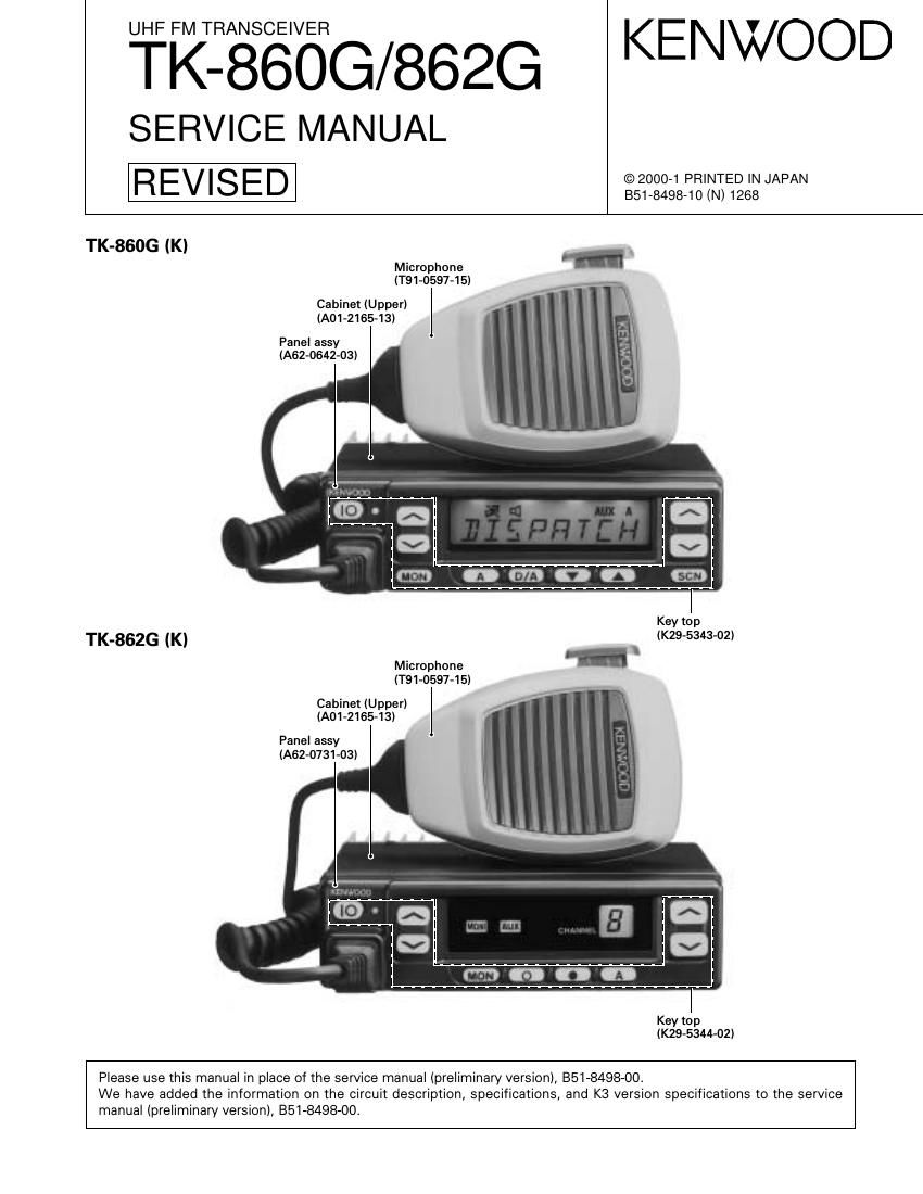
Kenwood TK 860 G Service Manual

This is the 67 pages manual for Kenwood TK 860 G Service Manual.
Read or download the pdf for free. If you want to contribute, please mail your pdfs to info@audioservicemanuals.com.

Page: 1 / 67
left right
Kenwood TK 860 G Service Manual

Extracted text from Kenwood TK 860 G Service Manual (Ocr-read)


Page 1

2 TK-860G/862G CONTENTS / GENERAL GENERAL INTRODUCTION SCOPE OF THIS MANUAL This manual is intended for use by experienced techni- cians familiar with similar types of commercial grade com- munications equipment. It contains all required service in- formation for the equipment and is current as of the publica- tion data. Changes which may occur after publication are covered by either Service Bulletins or Manual Revisions. These are issued as required. ORDERING REPLACEMENT PARTS When ordering replacement parts or equipment informa- tion, the full part identification number should be included. This applies to all parts : components, kits, or chassis. If the part number is not known, include the chassis or kit number of which it is a part, and a sufficient description of the re- quired component for proper identification. PERSONNEL SAFETY The following precautions are recommended for person- nel safety : - DO NOT transmit if someone is within two feet (0.6 meter) of the antenna. - DO NOT transmit until all RF connectors are verified se- cure and any open connectors are properly terminated. - SHUT OFF and DO NOT operate this equipment near electrical blasting caps or in an explosive atmosphere. - All equipment should be properly grounded before power-up for safe operation. - This equipment should be serviced by a qualified techni- cian only. PRE-INSTALLATION CONSIDERNATIONS 1. UNPACKING Unpack the radio from its shipping container and check for accessory items. If any item is missing, please contact KENWOOD immediately. 2. LICENSING REQUIREMENTS Federal regulations require a station license for each ra- dio installation (mobile or base) be obtained by the equip- ment owner. The licensee is responsible for ensuring trans- mitter power, frequency, and deviation are within the limits permitted by the station license. Transmitter adjustments may be performed only by a li- censed technician holding an FCC first, second or general class commercial radiotelephone operators license. There is no license required to install or operate the radio. CONTENTS GENERAL ................................................................. 2 SYSTEM SET-UP ..................................................... 4 OPERATING FEATURES ......................................... 5 REALIGNMENT ...................................................... 10 INSTALLATION ...................................................... 20 CIRCUIT DESCRIPTION ......................................... 24 SEMICONDUCTOR DATA ..................................... 29 DESCRIPTION OF COMPONENTS ....................... 31 PARTS LIST ............................................................ 33 EXPLODED VIEW .................................................. 42 PACKING ................................................................ 44 ADJUSTMENT ....................................................... 45 PC BOARD VIEWS DISPLAY UNIT (X54-3270-10) : TK-860G ........ 54 DISPLAY UNIT (X54-3280-10) : TK-862G ........ 55 PLL/VCO (X58-4670-XX) .................................. 56 TX-RX UNIT (X57-5960-XX) (A/2) ................... 57 TX-RX UNIT (X57-5960-XX) (B/2) .................... 63 SCHEMATIC DIAGRAM ........................................ 67 BLOCK DIAGRAM .................................................. 75 LEVEL DIAGRAM ................................................... 78 TERMINAL FUNCTION ......................................... 80 SPECIFICATIONS ................................................... 81

Page 2

3 TK-860G/862G 1 3 + -“ 7 6 13 15 5. INSTALLATION PLANNING -“ CONTROL STATIONS 5-1. Antenna system Control station. The antenna system selection depends on many factors and is beyond the scope of this manual. Your KENWOOD dealer can help you select an antenna sys- tem that will best serve your particular needs. 5-2. Radio location Select a convenient location for your control station radio which is as close as practical to the antenna cable entry point. Secondly, use your systems power supply (which supplies the voltage and current required for your system). Make sure sufficient air can flow around the radio and power supply to allow adequate cooling. SERVICE This radio is designed for easy servicing. Refer to the schematic diagrams, printed circuit board views, and align- ment procedures contained in this manual. Note When you modify your radio as described in system set- up, take the following precaution. The rating of pin 7 (SB) of the accessory connector cable (KCT-19) on the rear of the radio is 13.6V (1A). Insert a 1A fuse if you use the SB pin for external equipment. Accessory connector cable (KCT-19) If you do not intend to use the 3.5-mm jack for the exter- nal speaker, fit the supplied speaker-jack cap (B09-0235-05) to stop dust and sand getting in. Speaker-jack cap (B09-0235-05) 3. PRE-INSTALLATION CHECKOUT 3-1. Introduction Each radio is adjusted and tested before shipment. How- ever, it is recommended that receiver and transmitter opera- tion be checked for proper operation before installation. 3-2. Testing The radio should be tested complete with all cabling and accessories as they will be connected in the final installa- tion. Transmitter frequency, deviation, and power output should be checked, as should receiver sensitivity, squelch operation, and audio output. QT equipment operation should be verified. 4. PLANNING THE INSTALLATION 4-1. General Inspect the vehicle and determine how and where the radio antenna and accessories will be mounted. Plan cable runs for protection against pinching or crush- ing wiring, and radio installation to prevent overheating. 4-2. Antenna The favored location for an antenna is in the center of a large, flat conductive area, usually at the roof center. The trunk lid is preferred, bond the trunk lid and vehicle chassis using ground straps to ensure the lid is at chassis ground. 4-3. Radio The universal mount bracket allows the radio to be mounted in a variety of ways. Be sure the mounting surface is adequate to support the radios weight. Allow sufficient space around the radio for air cooling. Position the radio close enough to the vehicle operator to permit easy access to the controls when driving. 4-4. DC Power and wiring 1. This radio may be installed in negative ground electrical systems only. Reverse polarity will cause the cable fuse to blow. Check the vehicle ground polarity before installa- tion to prevent wasted time and effort. 2. Connect the positive power lead directly to the vehicle battery positive terminal. Connecting the Positive lead to any other positive voltage source in the vehicle is not rec- ommended. CAUTION If DC power is to be controlled by the vehicle ignition switch, a switching relay should be used to switch the posi- tive power lead. The vehicle ignition switch then controls DC to the relay coil. 3. Connect the ground lead directly to the battery negative terminal. 4. The cable provided with the radio is sufficient to handle the maximum radio current demand. If the cable must be extended, be sure the additional wire is sufficient for the current to be carried and length of the added lead. GENERAL

Page 28

29 TK-860G/862G SEMICONDUCTOR DATA Terminal function Pin No. Name I/O Function 1 EMGT O External MIC control. Mobile MIC : H 2 DTMF O DTMF/2TONE/BEEP output. 3 2TN I 2TONE decode pulse input. 4 DTMSTD I DTMF decode detect. Detect : H 5 SIM I Destination select. 6 BYTE I +5V (5C). 7 CNVSS I GND. 8 AFSTB O Base band IC strobe/reset output. 9 AFFCLK O Base band IC frame detect reset/ system reset output. 10 RESET I Reset. 11 XOUT O Clock output. 12 VSS -“ GND. 13 XIN I Clock input. 14 VCC -“ +5V. 15 NC I Pull up. 16 MICDAT I/O MIC data input/output. 17 AUX3 I/O Option board port 3. SmarTrunk : Clock output. 18 NC -“ NC. 19 OE I Output enable control sift register. 20 NC -“ NC. 21 EEPDAT I/O EEPROM data input/output. 22 TO O QT/DQT modulation output. 23 AUX1 I Option board port 1. SmarTrunk : Req/Ack input. 24 SFTSTB1 O Shift register strobe output. 25 DACSTB O D/A converter enable output. 26 PTT I PTT. PTT on : L 27 NC -“ NC. 28 NC -“ NC. 29 AUX4 O Option board port 4. SmarTrunk : Data output. 30 AUX2 I/O Option board port 2. SmartTrunk : Data input. 31 PA O MIC audio line sw control. PA : H 32 KOUT2 O Key scan output 2. 33 TXD O Serial data. PTT on : L 34 HOOK I HOOK/RXD. On hook : L 35 KOUT1 O Key scan output 1. 36 KOUT0 O Key scan output 0. Pin No. Name I/O Function 37 RDY I Pull up. 38 NC -“ NC. 39 HOLD I Not used. 40,41 NC -“ NC. 42 RD O READ signal. 43 NC -“ NC. 44 WR O WRITE signal. 45 LCDCS O LCD chip enable output. 46 CNTDAT O Common data output. (LCD, SHIFT REG, VOL, Audio processor) 47 CNTCLK O Common clock output. (EEPROM, LCD, SHIFT REG, VOL, Audio processor) 48 CSO -“ Chip select signal. 49 A19 -“ Not used. 50~59 A18~A9 -“ Flash memory address bus. 60 ACC -“ +5V. 61 A8 -“ Flash memory address bus. 62 VSS -“ GND. 63~70 A7~A0 -“ Flash memory address bus. 71~73 KIN0~KIN2 I Key scan input. 74 MON I [MON] key input. On : L 75 SCN I [SCN] key input. On : L 76 PLLUL I PLL unlock detect input. Unlock : L 77 PLLSTB O PLL strobe output. Latch : H 78 MUTE I RX audio mute. Mute : H 79~86 D7~D0 -“ Flash memory data bus. 87 PWR (EMG) I [PWR] key input (key interrupt). On : L 88 EMG/TXS I Emergency input (key interrupt). On : L 89 RFDAT O PLL data output. 90 RFCLK O PLL clock output. 91 NC -“ NC. 92 RSSQL I Receive signal strength indicator input. 93 ANLSQL I Analog squelch level input. 94 AVSS -“ GND. 95 TOI I QT/DQT signal input. 96 VREF -“ Reference voltage input. 97 AVCC -“ +5V. 98 DTMPD O DTMF IC power control. Power down : H 99 DTMCLK O DTMF IC decode clock output. 100 DTMDAT I DTMF IC decode data input. Microprocessor : 30622M4102GP (TX-RX Unit IC502)

Page 36

TK-860G/862G PARTS LIST 37 Ref. No. Address Parts No. Description Ref. No. Address Parts No. Description New Desti- parts nation New Desti- parts nation C554 CK73GB1H122K CHIP C 1200PF K C555 C92-0566-05 CHIP-TAN 10UF 6.3WV C556 CK73GB1C333K CHIP C 0.033UF K C557 CK73GB1C104K CHIP C 0.10UF K C558 CC73GCH1H101J CHIP C 100PF J C559 CK73GB1H102K CHIP C 1000PF K C560-563 CK73GB1C104K CHIP C 0.10UF K C564 C92-0507-05 CHIP-TAN 4.7UF 6.3WV C565,566 CK73GB1H472K CHIP C 4700PF K C567 CC73GCH1H101J CHIP C 100PF J C568 C92-0507-05 CHIP-TAN 4.7UF 6.3WV C569 CK73GB1E223K CHIP C 0.022UF K C570 CK73FF1C105Z CHIP C 1.0UF Z C571,572 CK73GB1H102K CHIP C 1000PF K C573 CK73FB1H563K CHIP C 0.056UF K C574 CC73GCH1H470J CHIP C 47PF J C575 CK73GB1H102K CHIP C 1000PF K C576 CK73GB1C104K CHIP C 0.10UF K C577,578 CK73GB1H103K CHIP C 0.010UF K C579 CC73GCH1H101J CHIP C 100PF J C580 CK73GB1C104K CHIP C 0.10UF K C581 CK73GB1H102K CHIP C 1000PF K C582 CK73GB1C473K CHIP C 0.047UF K C583 C92-0566-05 CHIP-TAN 10UF 6.3WV C584 CK73GB1H103K CHIP C 0.010UF K C585 CC73GCH1H101J CHIP C 100PF J C587 CK73GB1H103K CHIP C 0.010UF K C589 C92-0606-05 CHIP-TAN 4.7UF 10WV C590 CK73GB1H102K CHIP C 1000PF K C594 CK73GB1H102K CHIP C 1000PF K C596 CK73GB1H102K CHIP C 1000PF K C597 CC73GCH1H101J CHIP C 100PF J C598 CK73GB1H102K CHIP C 1000PF K C599 CC73GCH1H101J CHIP C 100PF J C600 CK73GB1H102K CHIP C 1000PF K C601,602 CC73GCH1H101J CHIP C 100PF J C603 CK73GB1H102K CHIP C 1000PF K C604-606 CC73GCH1H101J CHIP C 100PF J C608-610 CC73GCH1H101J CHIP C 100PF J C611,612 CK73GB1H471K CHIP C 470PF K C613 CC73GCH1H101J CHIP C 100PF J C615 CK73GB1H471K CHIP C 470PF K C616 CC73GCH1H101J CHIP C 100PF J C618 CK73GB1H102K CHIP C 1000PF K C620 CK73GB1H471K CHIP C 470PF K C621 CK73GB1H102K CHIP C 1000PF K C623 CK73GB1H102K CHIP C 1000PF K C626 CK73GB1C104K CHIP C 0.10UF K C628 CK73GB1C104K CHIP C 0.10UF K C629 CC73GCH1H470J CHIP C 47PF J C630 C92-0507-05 CHIP-TAN 4.7UF 6.3WV C631 CK73GB1H103K CHIP C 0.010UF K C632 CK73GB0J105K CHIP C 1.0UF K C633 CK73GB1C104K CHIP C 0.10UF K C720 C92-0566-05 CHIP-TAN 10UF 6.3WV CN1 E40-6047-05 PIN ASSY CN2 E40-6021-05 FLAT CABLE CONNECTOR CN3 E40-3247-05 PIN ASSY CN4 E40-5737-05 PIN ASSY CN5 E40-5738-05 PIN ASSYCN7 E40-3247-05 PIN ASSY CN8 E40-3246-05 PIN ASSY CN501 E40-6021-05 FLAT CABLE CONNECTOR J1 E11-0442-05 3.5D PHONE JACK (3P) J501 E08-0877-05 MODULAR JACK W1 E37-0856-05 PROCESSED LEAD WIRE F1 F53-0108-05 FUSE - J31-0543-05 COLLAR (LH-5-1.5) CF1 L72-0959-05 CERAMIC FILTER CF2 L72-0973-05 CERAMIC FILTER L1 L40-1005-34 SMALL FIXED INDUCTOR (10UH/8) L2-4 L40-3381-86 SMALL FIXED INDUCTOR (0.33U/160) L5 L34-4530-05 COIL L6 L40-8275-77 SMALL FIXED INDUCTOR (82NH/1608) L7 L40-5685-85 SMALL FIXED INDUCTOR (0.56U/252) K3 L7 L40-6885-85 SMALL FIXED INDUCTOR (0.68U/252) K,M L8 L40-8285-85 SMALL FIXED INDUCTOR (0.82U/252) L9 L40-1575-77 SMALL FIXED INDUCTOR (15NH/1608) L10 L40-2775-77 SMALL FIXED INDUCTOR (27NH/1608) L11,12 L40-1575-34 SMALL FIXED INDUCTOR (15NH/8) L13 L79-1585-05 HELICAL BLOCK K,M L13 L79-1591-05 HELICAL BLOCK K3 L14 L40-1875-77 SMALL FIXED INDUCTOR (18NH/1608) K,M L14 L40-2775-77 SMALL FIXED INDUCTOR (27NH/1608) K3 L15 L40-4775-77 SMALL FIXED INDUCTOR (47NH/1608) L16 L40-6875-34 SMALL FIXED INDUCTOR (68NH/8) L17 L40-1875-77 SMALL FIXED INDUCTOR (18NH/1608) L18 L40-1075-34 SMALL FIXED INDUCTOR (10NH/8) L19 L40-1085-77 SMALL FIXED INDUCTOR (100NH/160) K3 L19 L40-5675-77 SMALL FIXED INDUCTOR (56NH/1608) K,M L20 L40-1875-77 SMALL FIXED INDUCTOR (18NH/1608) K,M L20 L40-2775-77 SMALL FIXED INDUCTOR (27NH/1608) K3 L21 L34-4478-05 AIR-CORE COIL L22 L79-1585-05 HELICAL BLOCK K,M L22 L79-1591-05 HELICAL BLOCK K3 L24 L92-0179-05 FERRITE CHIP L26 L40-3375-34 SMALL FIXED INDUCTOR (33NH/8) L27 L40-1575-34 SMALL FIXED INDUCTOR (15NH/8) K,M L27 L40-1875-34 SMALL FIXED INDUCTOR (18NH/8) K3 L29 L34-1185-05 AIR-CORE COIL L30,31 L34-1039-05 AIR-CORE COIL L32 L34-4478-05 AIR-CORE COIL L33 L92-0179-05 FERRITE CHIP L35 L40-2775-77 SMALL FIXED INDUCTOR (27NH/1608) K3 L501 L92-0138-05 FERRITE CHIP L503,504 L92-0138-05 FERRITE CHIP L510 L92-0138-05 FERRITE CHIP X1 * L77-1826-05 TCXO (16.8M) X501 L77-1708-05 CRYSTAL RESONATOR (3.579545MHZ) X502 L78-0462-05 RESONATOR (9.8304M/8*2.5) XF1 * L71-0551-15 MCF (49.95MHZ/5.0K) CP501-505 R90-0741-05 MULTIPLE RESISTOR CP508-514 R90-0741-05 MULTIPLE RESISTOR CP516-524 R90-0741-05 MULTIPLE RESISTOR CP526,527 R90-0741-05 MULTIPLE RESISTOR CP529-536 R90-0741-05 MULTIPLE RESISTOR CP538 R90-0741-05 MULTIPLE RESISTORTX-RX UNIT (X57-5960-XX)

Page 66

KENWOOD CORPORATION14-6, Dogenzaka 1-chome, Shibuya-ku, Tokyo 150-8501, Japan KENWOOD SERVICE CORPORATIONP.O. BOX 22745, 2201 East Dominguez Street, Long Beach, CA 90801-5745, U.S.A. KENWOOD ELECTRONICS CANADA INC.6070 Kestrel Road, Mississauga, Ontario, Canada L5T 1S8 KENWOOD ELECTRONICS DEUTSCHLAND GMBHRembrΓΌcker Str. 15, 63150 Heusenstamm, Germany KENWOOD ELECTRONICS BELGIUM N.V.Mechelsesteenweg 418 B-1930 Zaventem, Belgium KENWOOD ELECTRONICS FRANCE S.A.13, Boulevard Ney, 75018 Paris, France KENWOOD ELECTRONICS U.K. LIMITEDKENWOOD House, Dwight Road, Watford, Herts., WD1 8EB United Kingdom KENWOOD ELECTRONICS EUROPE B.V.Amsterdamseweg 37, 1422 AC Uithoorn, The Netherlands KENWOOD ELECTRONICS ITALIA S.p.A.Via G. Sirtori, 7/9 20129 Milano, Italy KENWOOD IBERICA S.A.Bolivia, 239-08020 Barcelona, Spain KENWOOD ELECTRONICS AUSTRALIA PTY. LTD.(A.C.N. 001 499 074) 16 Giffnock Avenue, Centrecourt Estate, North Ryde, N.S.W. 2113 Australia KENWOOD ELECTRONICS (HONG KONG) LTD.Unit 3712-3724, Level 37, Tower one Metroplaza, 223 Hing Fong Road, Kwai Fong, N.T., Hong Kong KENWOOD ELECTRONICS TECHNOLOGIES(S) PTE LTD.Sales Marketing Division 1 Ang Mo Kio Street 63, Singapore 569110 TK-860G/862G