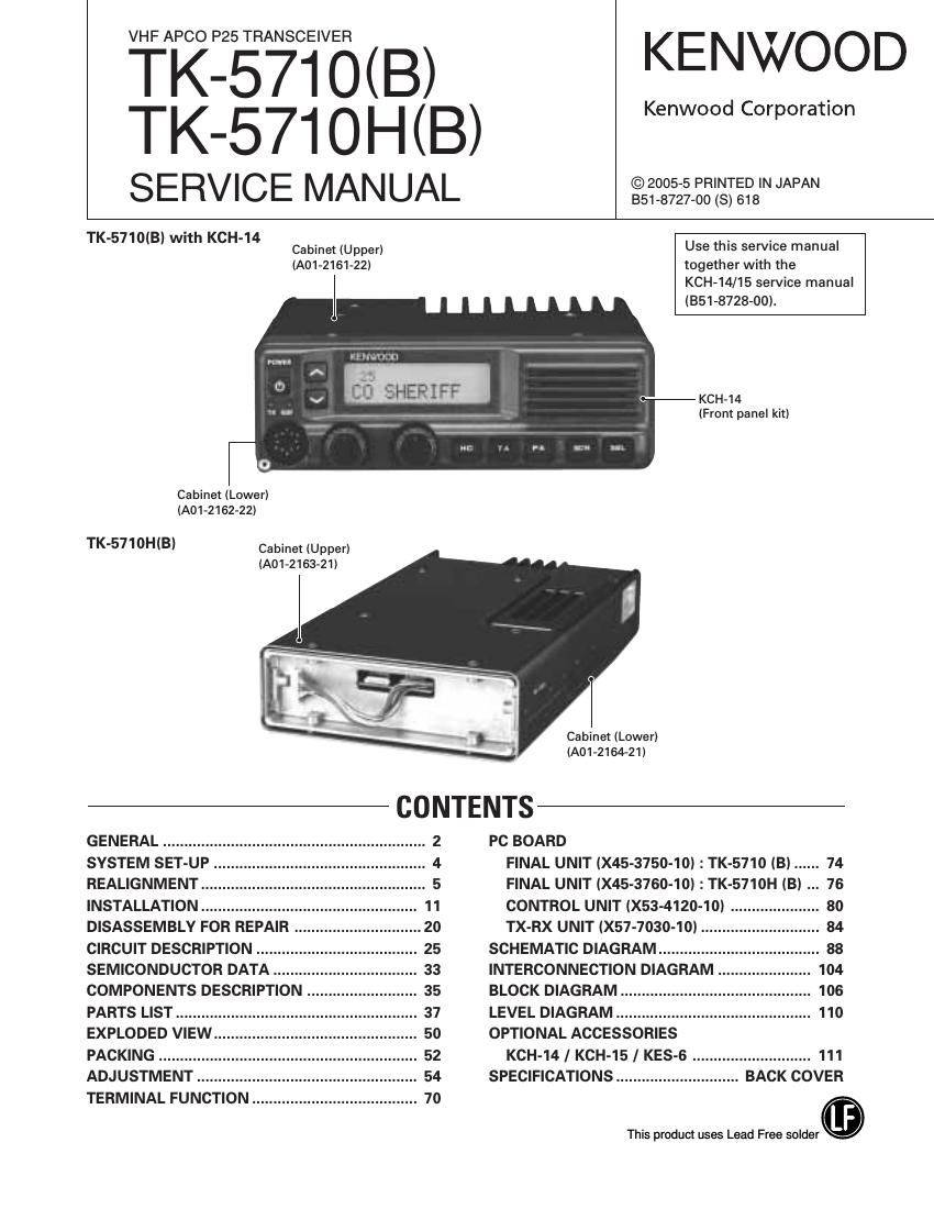
Kenwood TK 5710 Service Manual

This is the 124 pages manual for Kenwood TK 5710 Service Manual.
Read or download the pdf for free. If you want to contribute, please mail your pdfs to info@audioservicemanuals.com.

Page: 1 / 124
left right
Kenwood TK 5710 Service Manual

Extracted text from Kenwood TK 5710 Service Manual (Ocr-read)


Page 1

VHF APCO P2

TK-
TK-

55m7sciwi3(B) KENWOOD
571 O H (B) Kenwood Corporation

SERVICE MAN UAL ai9§:2-2.22'gi:?8'NJAPA~

TK-5710(B) with KCH-14

Cabinet (Upper) Use this service manual
(A01-2161-22) together with the
KCH-14/15 service manual
(351-8728-00).


(Front panel kit)

Ca binet (Lower)
(A01-2162-22)

TK-5710H(BI

Cabinet (Upper)
(A01-2163-21)

Cabinet (Lower)
(A01-2164-21)

GENERAL ................
SYSTEM SET-UP
REALIGNMENT
INSTALLATION
DISASSEMBLY FOR

CIRCUIT DESCRIPTION
SEMICONDUCTOR DATA
COMPONENTS DESCRIPTION ..

PARTS LIST .............
EXPLODED VIEW
PACKING ..........
ADJUSTMENT

TERMINAL FUNCTION .....

CONTENTS


PC BOARD
4 FINAL UNIT (X45-3750-10) : TK-5710 (B) ...... 74
5 FINAL UNIT (X45-3760-10) : TK-5710H (B) 76
. 11 CONTROL UNIT (X53-4120-10) . 80
REPAIR . .. 20 TX-RX UNIT (X57-7030-10) . 84
. 25 SCHEMATIC DIAGRAM... . 88
. 33 INTERCONNECTION DIAGRAM 104
. 35 BLOCK DIAGRAM.. 106
. 37 LEVEL DIAGRAM ...... .. 110
. 50 OPTIONAL ACCESSORIES
. 52 KCH-14/ KCH-15 / KES-6 ............................ 111
. 54 SPECIFICATIONS ............ BACK COVER

This product uses Lead Free solder.

Page 2

TK-5710lB)/5710H(Bl

GENERAL

INTRODUCTION

SCOPE OF THIS MANUAL

This manual is intended for use by experienced techni-
cians familiar with similar types of commercial grade com-
munications equipment. It contains all required service in-
formation for the equipment and is current as of this publica-
tion date. Changes which may occur after publication are
covered by either Service Bulletins or Manual Revisions,
which are issued as required.

ORDERING REPLACEMENT PARTS

When ordering replacement parts or equipment informa
tion, the full part identification number should be included.
This applies to all parts : components, kits, and chassis. If
the part number is not known, include the chassis or kit
number of which it is a part and a sufficient description of
the required component, for proper identification.

PERSONAL SAFETY

The following precautions are recommended for personal

safety :

0 DO NOT transmit if someone is within two feet (0.6
meter) of the antenna.

. DO NOT transmit until all RF connectors are secure and
any open connectors are properly terminated.

0 SHUT OFF this equipment when near electrical blasting
caps or while in an explosive atmosphere.

. All equipment should be properly grounded before
power»up for safe operation.

. This equipment should be serviced by only qualified
technicians.

PRE-INSTALLATION CONSIDERATIONS

1. UNPACKING

Unpack the radio from its shipping container and check
for accessory items. If any item is missing, please contact
KENWOOD immediately.

2. LICENSING REQUIREMENTS

Federal regulations require a station license for each
radio installation (mobile or base) be obtained by the
equipment owner. The licensee is responsible for ensuring
transmitter power, frequency, and deviation are within the
limits permitted by the station license.

Transmitter adjustments may be performed only by a
licensed technician holding an FCC first, second or general
class commercial radiotelephone operators license. There
is no license required to install or operate the radio.

3. PRE-INSTALLATION CHECKOUT
3-1.lntroduc1ion

Each radio is adjusted and tested before shipment.
However, it is recommended that receiver and transmitter
operation be checked for proper operation before
installation.

3-2. Testing

The radio should be tested complete with all cabling and
accessories as they will be connected in the final installa
tion. Transmitter frequency, deviation, and power output
should be checked, as should receiver sensitivity, squelch
operation, and audio output. Signaling equipment operation
should be verified.

4. PLANNING THE INSTALLATION
4-1. General

inspect the vehicle and determine how and where the
radio antenna and accessories will be mounted.

Plan cable runs for protection against pinching or crush-
ing wiring, and radio installation to prevent overheating.

4-2. Antenna

The favored location for an antenna is in the center of a
large, flat conductive area, usually at the roof center. The
trunk lid is preferred, bond the trunk lid and vehicle chassis
using ground straps to ensure the lid is at chassis ground.

Page 30

TK-5710(B)/5710H(B)

CIRCUIT DESCRIPTION

30

RX VCO 2 output a lst local receive signal. When the STR
logic is low, the TX VCO output a transmit carrier.

The voltage control terminals, "CV" and "ASSIST", are
controlled by the PLL lC (lC400) and rheostat lC (IC401) and
the output frequency changes continuously according to the
applied voltage. For the modulation input terminal, "MOD,
the output frequency changes according to the applied
voltage. This is used to modulate the VCO output. "MOD"
works only when " STR" is low.

5-3. Rheostat IC (IC401)

The rheostat lC (IC401) is connected to the VCO voltage
control terminal, "ASSIST", and quickly controls the VCO
oscillation frequency. However, its accuracy is low and the
VCO frequency cannot be matched accurately with the
desired transmit carrier or the 1st local receive signal.

The rheostat [C is controlled by the CPU (lC703) through
the 3-line "PCS", "DAT", "CLK" serial bus.

5-4. PLL IC (IC400)

PLL lC compares the differences in phases of the VCO
oscillation frequency and the VC> returns the difference to the VCO CV terminal and realizes
the Phase Locked Loop" for the return control. This allows
the VCO oscillation frequency to accurately match (lock) the

desired frequency.

When the frequency is controlled by the PLL, the
frequency convergence time increases as the frequency
difference increases when the set frequency is changed. To
supplement this, the rheostat IC is used before control by the
PLL lC to bring the VCO oscillation frequency close to the
desired frequency. As a result, the VCO CV voltage does not
change and is always stable at approximately 2 V.

The desired frequency is set for the PLL lC by the CPU
(IC703) through the 3-Iine "EP", "DAT", "CLK" serial bus.
Whether the PLL IC is locked or not is monitored by the CPU
through the "UL" signal line. if the VCO is not the desired
frequency (unlock), the "UL" logic is low.

5-5. Local Switch (D435, D436)

The connection destination of the signal output from the
amplifier (0419) is changed with the diode switch (D435) that
is controlled by the transmission power supply, ST, and the
diode switch (D436) that is controlled by the receive power
supply, 8R.

If the 8T logic is high, it is connected to a transmitAside
pre-pre-drive amplifier (0150). If the 8R logic is high, it passes
through the local amplifier (0210) and then is connected to a
receiveaside mixer (A400).

- 5c
sw
ivco 1/2»
0409 0413,0414
l % 78CL+ RX «ASSISTi
SCL SW SCL % W" VCOLZ SC slc ST
0405 RX vco 1-> 1 l
0407 0408 SC L
sw sw ) "3400 0416 D435,D436
8CL 4» TX T/R pre-pre-drive
8CL - MO -> (0150)
STR TX vco ' 4 l
163MHz ASSHST 3- Local
1c4o1 1c402 l AMP
POTENTIO vco X400 50 (0201)
- ASSIST» 7 3.3V» 8R
METER TUNE vcxo % y
7 MB » /\/
5: SEE DOUBLER RF AMP
DAT 0403 0418
Fig. 11 PLL block diagram

6. Control Circuit

The control circuit consists of CPU (lC703) and its periph-
eral circuits. It controls the TX-RX unit and transfers data to
the Control unit. lC703 mainly performs the following;

1) Switching between transmission and reception by PTT
signal input.

2) Reading system, zone, frequency, and program data from
the memory circuit.

3) Sending frequency program data to the PLL.

4) Controlling squelch on/off by the DC voltage from the
squelch circuit.

5) Controlling the audio mute circuit by decode data input.

6-1. Memory Circuit

Memory circuit consists of the CPU (lC703) and a flash
memory (lC712). A flash memory has a capacity of 16M bits
and contains the transceiver control program for the CPU. It
also stores the data for transceiver channels and operating
parameter that are written by the FPU. This program can be
easily written from an external devices.

The EEPROM (lC701) stores the last channel data, the
scan on status, and other parameters.

I Flash memory
Note : The flash memory (lC712) stores the data that is

Page 32

TK-5710lB)/5710H(B)

CIRCUIT DESCRIPTION

8. Signaling Circuit
8-1. Encode (OT/DOT/DTMF/MSK)

Each signaling data signal of OT, DOT, DTMF and MSK is
generated by the DSP circuit, superposed on a modulation
signal and output from pin 16 of the CODEC lC (IC724).

The modulation balance of the OT/DQT signal is adjusted
by the D/A converter(lC738) and the resulting signal is routed
to the modulation input of the VCO and VCXO (X400).

The each deviation of the TX OT, DOT, DTMF and MSK
tone is adjusted by changing the output level of the CODEC
lC and the resulting signal is routed to VCO and VCXO. The
RX DTMF tone is output from pin 15 ot the CODEC IC,
passes through the receive audio signal system, and is out»
put from the speaker.

8-2. Decode (QT/DQT/DTMF/Z-tone/MSK)
The audio signal is removed from the FM detection signal
sent to the DSP circuit and the resulting signal is decoded.

9. Compander Circuit

The term "compander" means compressor and expander.
The compander reduces noise by utilizing a compressor and
an expander.

The transceiver contains DSP IC (IC715) to perform this
operation. The transceiver compander can be turned on or
off using the FPU.

32