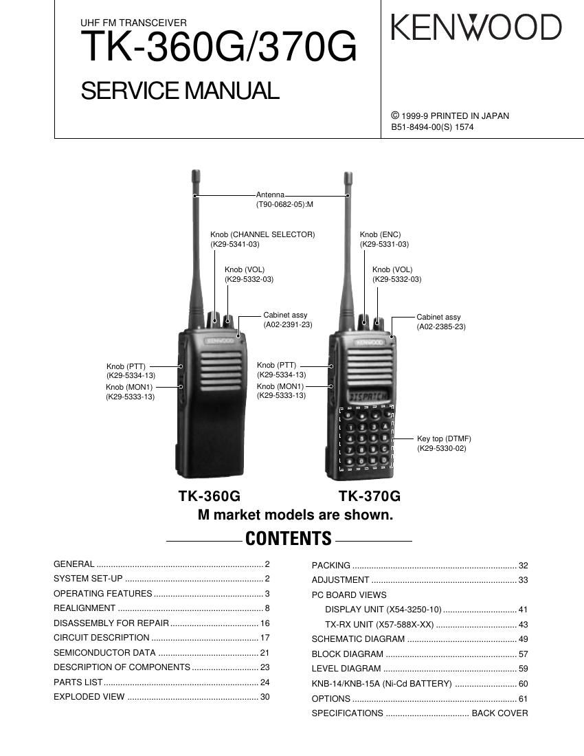
Kenwood TK 360 G Service Manual

This is the 50 pages manual for Kenwood TK 360 G Service Manual.
Read or download the pdf for free. If you want to contribute, please mail your pdfs to info@audioservicemanuals.com.

Page: 1 / 50
left right
Kenwood TK 360 G Service Manual

Extracted text from Kenwood TK 360 G Service Manual (Ocr-read)


Page 1

TK-360G/370G 2 GENERAL / SYSTEM SET-UP INTRODUCTION SCOPE OF THIS MANUAL This manual is intended for use by experienced technicians familiar with similar types of commercial grade communications equipment. It contains all required service information for the equipment and is current as of the publication date. Changes which may occur after publication are covered by either Service Bulletins or Manual Revisions. These are issued as required. ORDERING REPLACEMENT PARTS When ordering replacement parts or equipment information, the full part identification number should be included. This applies to all parts, components, kits, or chassis. If the part number is not known, include the chassis or kit number of which it is a part, and a sufficient description of the required component for proper identification. PERSONNEL SAFETY The following precautions are recommended for personnel safety: lDO NOT transmit until all RF connectors are verified secure and any open connectors are properly terminated. lSHUT OFF and DO NOT operate this equipment near electrical blasting caps or in an explosive atmosphere. lThis equipment should be serviced by a qualified technician only. SERVICE This radio is designed for easy servicing. Refer to the schematic diagrams, printed circuit board views, and alignment procedures contained within. NOTE WE CANNOT guarantee oscillator stability when using channel element manufactured by other than KENWOOD or its authorized agents. Unit X57-5880-XX X54-3250-XX Model & Frequency range Remarks Whip Antenna Charger Battery 16 Key destination 0-10 0-11 0-21 0-10 TK-360GK_ÐOPÐ M_Ð 450~470MHzIF1 : 49.95MHz_ OP OPÐ TK-370GK__LOC : 50.4MHz OP_ M__ _ _ SYSTEM SET-UP Merchandise received License and frequency allocated by FCC Choose the type of transceiver Transceiver programming Delivery Are you using the speaker microphone?TX/RX 450~470 4.0WTK-360G K,M TK-370G K,M Frequency range (MHz) RF power Type A personal computer (IBM PC or compatible), programming interface (KPG-22), and programming software (KPG-56D) are required for programming. (The frequency, TX power HI/LOW, and signalling data are programmed for the transceiver.) YES NO KMC-17 or KMC-21 Speaker microphone (Option)

Page 2

TK-360G/370G 3 OPERATING FEATURES 1. Operation Features ¥ TK-360G The transceiver is shown with the optional KNB-14 battery pack. q qq q qRotary encoder Your dealer can program the encoder as either Group Up/Down or Channel Up/Down (default setting). Rotate to select a group or channel. Also rotate to adjust the squelch in Squelch Adjustment mode. w ww w wLED indicator Lights red while transmitting. Lights green while receiving. Flashes orange while receiving a Code Squelch code or a Selective Call code, or a 2-Tone or DTMF signal that matches the one set up in your transceiver. Flashes red when the battery power is low while transmitting. e ee e ePower switch/ Volume control Turn clockwise to switch ON the transceiver. Rotate to adjust the volume. To switch OFF the transceiver, turn counterclockwise fully. r rr r rPTT (Push-to-Talk) switch Press this switch, then speak into the microphone to call a station. t tt t tSide 1 key This is a PF (Programmable Function) key. Press it to activate its auxiliary function (page 4). y yy y ySide 2 key This is a PF (Programmable Function) key. Press it to activate its auxiliary function (page 4). Programmable Auxiliary Functions Side 1 key and Side 2 key can each be programmed with one of the following auxiliary functions: ¥Monitor A (Monitor UnmuteÐMomentary): Press and hold the Monitor key to hear background noise. Release the key to return to normal operation. ¥Monitor B (Monitor UnmuteÐToggle): Momentarily press the Monitor key to hear background noise. Press the key again to return to normal operation. ¥Monitor C (Carrier SquelchÐMomentary): Press and hold the Monitor key to deactivate QT, DQT, 2-Tone, or DTMF signalling. Release the key to return to normal operation. ¥Monitor D (Carrier SquelchÐToggle): Momentarily press the Monitor key to deactivate QT, DQT, 2-Tone, or DTMF signalling. Press the key again to return to normal operation. ¥None: No function. ¥RF Power Lo: Press the RF Power Lo key to toggle the output power of a channel between high and low. This can only be used for channels that have been programmed with high power. Pressing RF Power Lo while using a channel programmed with low power Microphone Speaker Antenna Channel selector Rotate to select a channel (1 ~ 8). LED indicator Lights red while transmitting. Lights green while receiving. Flashes orange while receiving a 2-Tone or DTMF signal that matches the one set up in your transceiver. Flashes red when the battery power is low while transmitting.Power switch/ Volume control Turn clockwise to switch ON the transceiver. Rotate to adjust the volume. To switch OFF the transceiver, turn counterclockwise fully. PTT (Push-to- Talk) switch Press this switch, then speak into the microphone to call a station. Side 2 key Press to activate its programmable function. Side 1 key Press to activate its programmable function. SP/MIC jacks Connect an optional speaker/ microphone here. The transceiver is shown with the optional KNB-14 battery pack. causes an error tone to sound. (When changing a channel from high to low power, all channels programmed with high power are changed to low.) ¥2-Tone Encode Select: To transmit using a 2-Tone code, press the PTT switch and the 2-Tone Encode Select key, then speak into the microphone in your normal voice. Release the PTT switch and 2-Tone Encode Select key to receive. ¥ TK-370G Antenna A 3 2 1 B 6 5 4 C 9 8 7 D 0 q qq q qe ee e e r rr r r t tt t t y yy y y u uu u u i ii i io oo o o !0 !0!0 !0 !0 w ww w w Microphone Speaker

Page 4

TK-360G/370G 5 OPERATING FEATURES 3. Display (TK-370G only) 9) Reverse (REV) (Note: C type only) When the REV switch is pressed, transmission can be performed with the receive frequency and receive signaling, and reception can be performed with the trasmit frequency and transmit signaling. When REV is on, HORN ALERT and PUBLIC ADDRESS do not work. 10) Selectable QT (SEL QT) (TK-370G M types only) When the SEL QT switch is pressed, QT frequency can be temporarily changed with the CH switch. 11) 2-Tone Encode Select (TK-370G only) 1Press the key programmed as 2-tone Encode Select. ¥ A pre-programmed 2-tone code name appears on the display. 2Press the key programmed as Channel Up and Channel Down to select you desired 2-tone code name. 3Press PTT switch and 2-Tone Encode Select key to transmit and release them to receive. Note: The code for the TK-360G is not selectable. You cannot change the tone in step 2 by using the Channel Up and Channel Down keys. 12) Redial (TK-370G only) Pressing this key when Group/Channel is shown, displays the previously transmitted DTMF code. Pressing [PTT] at this time, transmits the code that is currently displayed. 13) RF power low Used to temporarily switch transmission output to low power. Turning the function on enables: Hi®Low, Low®Low Key states are backed up, except in the PC mode when they are reset. 14) Scan (TK-370G only) Pressing this key starts scanning. Pressing this key again stops scanning. 15) Scan Del/Add (TK-370G only) This key switches the currently displayed channel between "Delete" and "Add". The "Add" channel is contained in the scan sequence, the "Delete" channel is not contained. In the scan mode, this key switches the channel between delete or add, temporarily. 16) Talk Around (TK-370G only) Press this key, the transceiver uses the receive frequency and tone for transmission. The operator can call the other party directly (without repeater). Press this key again, the talk around function goes off. 17) None An error operation beep sounds, and no action will occur. Use this function when the transceiver is required to be operated more simply. 4. Scan Operating (TK-370G only) 1) Scan types l Single Group Scan You can scan all valid (ADD) channels in the displayed group that can be selected with the group selector. l Multiple Group Scan You can scan all valid (ADD) channels in all valid (ADD) groups. 2) Scan Start Condition One or more non-priority channels must be added to all channels that can be scanned. The transceiver must be in normal receive mode (PTT off). When you activate the key programmed to the scan function, scan starts. The scan icon ("SCN") lights and "SCAN" is indicated on display. Icon Description Not used in this transceiver. Appears when the selected channel is busy. Appears when QT, DQT, DTFM, or 2- Tone decoding is deactivated (by pressing the Monitor key). Appears when you receive a Code Squelch, Selective Call, 2-Tone, or DTMF Signallling call. Also appears when you transmit using Code Squelch or Selective Call. Appears while scanning. Appears when using low power on the selected channel. Appears when the selected channel is included in the scanning sequence. Displays the selected channel, the squelch level, DTMF digits (when entering digits, confirming digits, or making a call), and messages received via Selective Call.

Page 19

TK-360G/370G 20 CIRCUIT DESCRIPTION Low battery warning The red LED flashes during transmission. The red LED flashes and a continuous beep sounds while PTT is pressed.Battery condition The battery voltage is low but the transceiver is still usable. The battery voltage is low and the transceiver is not able to make calls. 6. Control Circuit The control circuit consists of a microprocessor (IC13) and its peripheral circuits. It controls the TX-RX unit and transfers data to and from the display unit. IC13 mainly performs the following: (1) Switching between transmission and reception by the PTT signal input. (2) Reading system, group, frequency, and program data from the memory circuit. (3) Sending frequency program data to the PLL. (4) Controlling squelch on/off by the DC voltage from the squelch circuit. (5) Controlling the audio mute circuit by the decode data input. (6) Transmitting tone and encode data. 1) Frequency shift circuit The microprocessor (IC13) operates at a clock of 9.8304MHz. This oscillator has a circuit that shifts the frequency by BEAT SHIFT SW (Q31). 2) Memory circuit Memory circuit consists of the CPU (IC13) and a flash memory (IC12). A flash memory has a capacity of 2M bits that contains the transceiver control program for the CPU and data such as transceiver channels and operating features. This program can be easily written from an external device. Data, such as DTMF memorise and the operating status, are programmed into the EEPROM (IC10). l Flash Memory Note : The flash memory holds data such as written with the FPU (KPG-56D) and firmware program (User mode, Test mode, Tuning mode, etc.). This data must be rewritten when replacing the flash memory. l EEPROM Note : The EEPROM stores tuning data (Deviation, Squelch, etc.). Realign the transceiver after replacing the EEPROM. Fig. 9 Memory circuit IC13 IC12 CPUIC10 EEPROM FLASH 3) Low battery warning The battery voltage is monitored by the microprocessor (IC13). When the battery voltage falls below the voltage set by the Low Battery Warning adjustment, the LED flashes red to notify the operator that it is time to replace the battery. If the battery voltage falls even more (approx. 5.8V), a beep sounds and transmission is stopped. 7. Optional Board Terminal Terminals for mounting the option board are provided at the bottom edge of the TX-RX unit. The table below shows the correspondence between the board and terminals. Optional Board Terminal Function (CN5) Pin Name I/O Function 1 GND - GND 2 SB O Power output after power switch 3 AUX3 I/O Board control 4 TXAFI I Modulation output from board 5 AUX2 I/O Board control 6 AUX6 O Board control 7 AUX1 I Board control 8 AUX5 O Board control 9 AUX4 O Board control 10 TXAFO O Modulation input to board 11 5C O 5V 12 RXAFO O Received signal input to board 13 NC - NC 14 RXAFI I Received signal output from board 15 NC - NC 16 ALTTONE I ALART TONE output form board 17 NC - NC 18 NC - NC 19 NC - NC 20 GND - GND

Page 30

TK-360G/370G 31 CD 1 2 3 EXPLODED VIEW (TK-370G) Parts with the exploded numbers larger than 700 are not supplied. 2.5 44M2 M3 J32-0925-04 J 51 701 1 31 C 48 49 23 27 SP 16 A M2.6x4 :N09-2319-05 B M2x3.5 :N09-2331-05 C NUT :N14-0582-14 D NUT :N14-0583-04 F M2.6x6 :N30-2606-46 H M2x3 :N39-2030-46 I M2x5 :N67-2005-46 J f 2x4.5 :N78-2045-46 K f 2x3 :N79-2030-46 L f 2x5 :N83-2005-4643 JD 42 6 5 14 3 38 Lx8 IC1 I H H 18 705 20 21 DISPLAY unit 47 19 46 15B 3913 TX-RX unit (A/2) 26 A 28 B 11 702 25 J TX-RX unit (B/2) 17 F K 704 703 12 503722 52