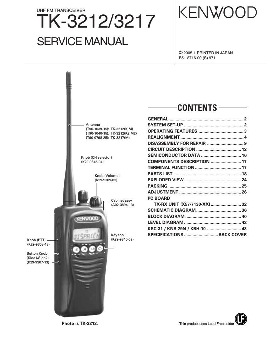
Kenwood TK 3217 Service Manual

This is the 47 pages manual for Kenwood TK 3217 Service Manual.
Read or download the pdf for free. If you want to contribute, please mail your pdfs to info@audioservicemanuals.com.

Page: 1 / 47
left right
Kenwood TK 3217 Service Manual

Extracted text from Kenwood TK 3217 Service Manual (Ocr-read)


Page 2

TK-3212/3217

GENERAL/SYSTEM SET-UP

INTRODUCTION

SCOPE OF THIS MANUAL

This manual is intended for use by experienced technicians
familiar with similar types of commercial grade
communications equipment. It contains all required service
information for the equipment and is current as of the
publication date. Changes which may occur after publication
are covered by either Service Bulletins or Manual Revisions.
These are issued as required.

ORDERING REPLACEMENT PARTS

When ordering replacement parts or equipment information,
the full part identification number should be included. This
applies to all parts, components, kits, or chassis. If the part
number is not known, include the chassis or kit number of
which it is a part, and a sufficient description of the required
component for proper identification.

Unit
Model TX-RX Unit Frequency range Remarks
&destination
TK-3ZIZ K,M X57-7l30-10 450~490MHZ
TK-3212 KZ' x57-713o-11 470~512MH2 'Fli38'85MHZ
M2 LOC : 38.4MHZ
TK-3217 M X57-7l30-21 440~480MHZ

SYSTEM SET-UP

Merchandise received

PERSONAL SAFETY

The following precautions are recommended for personal

safety:

I DO NOT transmit until all RF connectors are verified secure
and any open connectors are properly terminated.

I SHUT OFF and DO NOT operate this equipment near
electrical blasting caps or in an explosive atmosphere.

I This equipment should be serviced by a qualified technician only.

SERVICE

This transceiver is designed for easy servicing. Refer to
the schematic diagrams, printed circuit board views, and
alignment procedures contained within.

License and frequency allocated by FCC

Choose the type of transceiver

Frequency range (MHZ) RF power Type
TX/RX 450~490 4.0W TK-3212 (K,M)
TX/RX 470~512 4.0W TK-3212 (K2,M2)
TX/RX 440~480 4.0W TK-3217 (M)

Transceiver programming

A personal computer (IBM PC or compatible), programming

interface (KPG-22), and programming software (KPG»|00D)

are required for programming.

(The frequency, TX power HI/LOW, and signaling data are programmed
for the transceiver.)

( - - ) YES KRA-23 or KRA-27
A 7
re you usrng the optional antenna. 0 ti | t

NO

< - - )YES KMC-l 7 or KMC-21
m 7
Are you usrng the speaker Icrophone. S k r i r

NO

I Delivery I

(Option)

Page 17

TK-3212/3217

COMPONENTS DESCRIPTION [TERMINAL FUNCTION

TX-RX UNIT lX57-7130-XXI

Ref. No. Part name Description Ref. No. Part name Description
|C1 IC PLL system D1 Diode Ripple filter
ICi 01 IC Comparator (APC) D2 Varicap Frequency control / TX VCO
IC201 IC FM IF system D3 Varicap Frequency control / RX VCO
IC301 IC Audio processor D4 Varicap Frequency control / TX VCO
|C302 lC AF AMP D5 Varicap Frequency control / RX VCO
|C401,402 IC Voltage regulator/ 5v D6.7 Varicap Frequencv control / TX VCO
|C403 lC Voltage detector/ Reset D8,9 Varicap Frequency control / RX VCO
|C404 IC Voltage detector/ INT D10 Varicap Modulator
|C405 IC Microprocessor D1 1 Diode Current steering
|C406 IC EEPROM D101 Diode TX/RX RF switch
|C407 IC Frequency divider D102 Zener diode APC protect
Qi Transistor Tripler D103,104 Diode ANT switch
02 Transistor PLL IC Lin AMP D106 Diode ANT switch
03 FET VCO / RX D122 Diode ANT switch
04 FET VCO / TX D202 Diode TX/RX RF switch
05 Transistor DC switch / TX VCO D203-206 Varicap RF BPF tuning
06 Transistor RF buffer AMP D210 Varicap RF BPF tuning
Q7 Transistor DC switch / RX VCO D301 ,302 Diode Detector
08 Transistor Ripple filter D303 Diode isolation
09 Transistor RF AMP D401 Diode 5V protection
Oi 00 Transistor RF AMP D402 Diode Reverse protection
Oi Oi FET RF AMP D403 LED LED/ Red
Oi 02 FET TX drive AMP D404 LED LED/ Green
Oi03 FET TX final AMP
Oi 04 Transistor APC switch TERMINAL FUNCTION
Oi 05 FET APC switch I CN401
Oi O7 Transistor APC switch pin .
Oi 08 FET APC switch 0- Name 0 Fundmn
Oi 09 Transistor APC switch 1 B ' B 35 Vonage'
0202 Transistor W/N switch / RX 2 SB 0 SWlthd B
0203 Transistor [F AMP 3 AF' ' Am) in?
0204 FET Mixer 4 AFC 0 Audio output
0205 FET RF AMP 5 GND ' GND
0301 Transistor W/N switch / TX 5 UP ' EWOde' PU'SE input
0302 Transistor MIC AGC 7 DOWN l Encoder pulse input
0303 Transistor DC switch / SP mute 8 GND ' GND
0304 Transistor DC switch I CN402
O305 Transistor DC swttch / SP mute Pin
0306 FET SP mute switch No. Name "0 F"°°"
O316 FET SP mute switch 1 GND - GND
O40i Transistor LED switch / Red 2 NC - No connection
O402 Transistor LED switch / Green 3 SB 0 Switched B
0403 FET 5T sWitch 4 5M - Power supply
0404 Transistor 5R switch 5 GND - GND
0405 Transistor 5C switch 6 DI | Transfer data
0407,408 FET Beat shift switch 7 CL l Synchronization clock
0901 FET W/N switch / TX 8 CE | Chip enable
9 DO 0 Output data
10 GND - GND

17