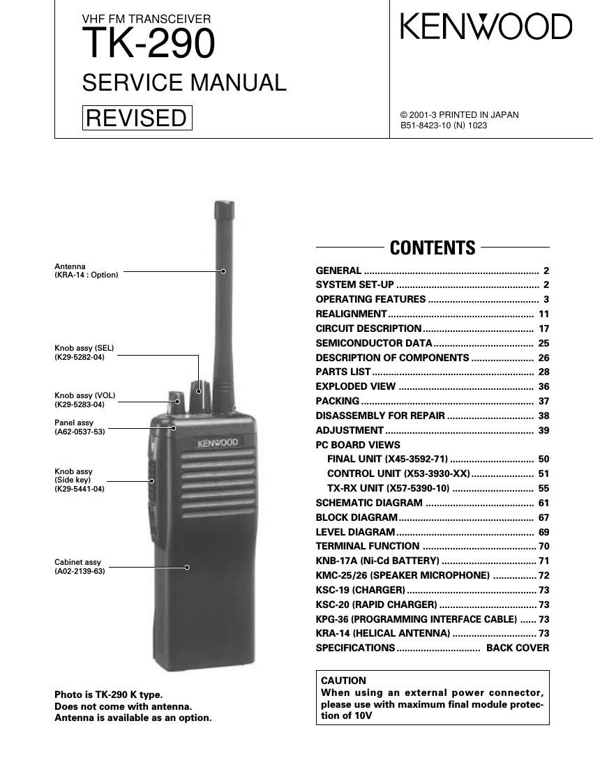
Kenwood TK 290 Service Manual

This is the 64 pages manual for Kenwood TK 290 Service Manual.
Read or download the pdf for free. If you want to contribute, please mail your pdfs to info@audioservicemanuals.com.

Page: 1 / 64
left right
Kenwood TK 290 Service Manual

Extracted text from Kenwood TK 290 Service Manual (Ocr-read)


Page 1

2 TK-290 GENERAL / SYSTEM SET-UP INTRODUCTION SCOPE OF THIS MANUAL This manual is intended for use by experienced techni- cians familiar with similar types of commercial grade com- munications equipment. It contains all required service in- formation for the equipment and is current as of the publica- tion data. Changes which may occur after publication are covered by either Service Bulletins or Manual Revisions. These are issued as required. ORDERING REPLACEMENT PARTS When ordering replacement parts or equipment informa- tion, the full part identification number should be included. This applies to all parts : components, kits, or chassis. If the part number is not known, include the chassis or kit number of which it is a part, and a sufficient description of the re- quired component for proper identification. PERSONNEL SAFETY The following precautions are recommended for person- nel safety : - DO NOT transmit until all RF connectors are verified se- cure and any open connectors are properly terminated. - SHUT OFF and DO NOT operate this equipment near electrical blasting caps or in an explosive atmosphere. - This equipment should be serviced by a qualified techni- cian only. SERVICE This radio is designed for easy servicing. Refer to the schematic diagrams, printed circuit board views, and align- ment procedures contained within. NOTE WE CANNOT guarantee oscillator stability when using channel element manufactured by other than KENWOOD or its authorized agents. FCC COMPLIANCE AND TYPE NUMBERS Model Type acceptance number Frequency range Compliance TK-290 ALH21893110 136~174MHz Parts 22,74,80,90 Unit X57-539X-XX X53-393X-XX X45-359X-XX DTMF Model &Frequency range Remarks keypad destination 0-10 0-11 0-12 2-71 TK-290 K 136~174MHz 1st IF : 44.85MHz -“ K2136~174MHz LOC : 45.305MHz Merchandise received License and frequency allocated by FCC Choose the type of transceiver Transceiver programming Are you using the optional antenna? Delivery Are you using the speaker microphone? TX/RX 136~174 5WTK-290 K,K2 Frequency range (MHz) RF power Type A personal computer (IBM PC or compatible), programming interface (KPG-36), and programming software (KPG-38D) are required for programming. (The frequency, and signalling data are programmed for the transceiver.) YES YES YES NO NO NO KRA-14 Helical antenna (Option) With antenna? KMC-25KMC-26 SYSTEM SET-UP

Page 2

3 TK-290 OPERATING FEATURES 1. Getting Acquainted 1-1. Key Descriptions TX/Busy/Battery low indicator Lights red while transmitting. Lights green while receiv- ing. Flashes red when the battery power is low while transmitting; replace or recharge the battery. Note : This indicator can be disabled by your dealer. Power switch/Volume control Turn clockwise to switch ON the transceiver. Turn coun- terclockwise, until a click sounds, to switch OFF the transceiver. Rotate to adjust the volume level. Selector Rotate this control to activate its programmable function (Page 8). Toggle switch Switch the toggle position to activate its programmable function (Page 8). Top 1 Top 2 Orange Side 1 Side 2 PTT (Push-To-Talk) switch Press this switch, then speak into the microphone to call a station.Press these PF (programmable function) keys to activate their programmable func- tions (Page 8) DTMF keypad (keypad models only) Press the keys on the telephone keypad to send DTMF tones. Universal connector Connect the external speaker/microphone (optional) here. Otherwise, keep the supplied cover in place. 1-2. Display Alphanumeric display Displays the operating group or channel number, or the group or channel name. When making a DTMF or 2 Tone call, the display will alternate between CALL and the channel. Also displays various menu functions. 7 Segment display Displays the operating group or channel number. Also displays tA (Talk Around), P1 (Priority1), P2 (Priority2), PP (Priority1 and Priority2), or HC (Home Channel); depend- ing on the function being used. A (Add) indicator Appears when a channel is added to the scanning se- quence. SCN (Scan) indicator Appears when Scan mode is active. MON (Monitor) indicator Appears when the monitor function is active. LO (Low) indicator Appears when low power is selected. OPT indicator Appears when Operator Selectable Tone is enabled. AUX (Auxiliary) indicator Appears when Aux is ON. Appears and blinks when the optional scrambler board is enabled. Note : The alphanumeric and 7 segment displays can be inverted if a PF key or the toggle switch is programmed with Invert Display (Page 8). ABAB SMA male type antenna connectorBattery pack release latch Microphone Display Speaker

Page 51

S R Q P O N M L K J I H G F E D C B A 1 2 3 4 5 6 7 8 9 10 11 12 13 14 D /6 B /6 F /6 E /6 J 72-0 705-2 2 A /6 L 101 C N 101 R 107 C 106 C 103 D 101 R 101 R 102 C 104 C 105 R 502 1 2 1 5C MBLE DTX LE DLA M PDICLCEQ 7Q6KI2T O G GLED G ND + R103 R 104 IC 10 1 1 1617 32 33 4 8 49 64 R 106R 108 D G ND TO GGLE R 55 D 18 D 14 IC 7 1 8 9 16 IC 2 IC 10 R 23R 22 1 1 4 5 8 8 9 16 D 11 D 17 D 19D 12 D 20D 13 R 54R 53 R 42R 41 R 40R 39 R 38R 37 R 52R 51R 50 C 7 L1 IN T S P+IN T S P-“ L2 R 66 R 67 C 6 C11 C 10 D 2 Q 5 L6 C 1 Q 6 B C E C16 R 9 R56 Q 8 C39 C 8 C5 R15 R 30 R 57 R 29 R 35 R 34 C 30 C 35 IC 3 1 4 5 8 R60 C 37 C 3 R10 R 11 R 63 T C O NTOPPT TA M PS WEX AFCIN AFCN CKESD G NDKEY 1KEY 2LC SPTTN /C S W5T BC LKD ATAES BSB5C MM IC EM ICA FAFEA FES P+S P-“M UTES D T OM AN DL A M PQ7Q6 R64 C 15 C 38 C 4 CP1 R 31 R 20 R 19 R 8 R7R6 IC 6 1345 Q 141235 IC 5 IC 4 1345 1345 C22 D 16 C 27 C 29 C 28 R 26 R 28 R 27 R 62 C N 1 1 R4 C12 + R 18 IC 1 R13R 12 C 13 C 43R 14 R 2 R1 R17 C 14 R 5 L9 Q 15 Q 7 DGS DGS DGS L3 L4 1 8 9 16 C 41 C 19 C 32 C 2 C31 R 3 R43 R 36R 44 R 33 R 32 C 45 C N 4 2 1 C46 D 15 R 45 R 46R 47 C N 3 1 6 R59R 48R 49 C 33 C 34 Q 6KI1P TTP TT EQ 7Q8 33 PC B OARD V IE W S C O NTR O L U NIT ( X 53-3 930-X X) - 1 1 : K - 1 2 : K 2 F o il s id e v ie w C om pon en t s id e Fo il s id e P atte rn 1 P atte rn 2 P atte rn 3 P atte rn 4 R ef N o. A ddre ss IC 101 3L D101 2J C on nect 1 a n d 4 5 3 5 4 R ef N o. A ddre ss IC 1 7J IC 2 11G IC 3 9L IC 4 12H IC 5 11H R ef N o. A ddre ss IC 6 11H IC 7 11F IC 10 11H Q5 9J Q6 8J R ef N o. A ddre ss Q7 8I Q8 9I Q14 8L Q15 8I D2 9J R ef N o. A ddre ss D11 9F D12 9H D13 9G D14 9F D15 12N R ef N o. A ddre ss D16 12G D17 9G D18 9E D19 9H D20 9G

Page 57

TK-290 TK-290 68 BLOCK DIAGRAM +BATT SBC 2SK 1824 RESET 44.85MHz 136~174MHz DET TCXO 16.8MHz 455kHz +B RSSI SQL 5RC 5CC SW 5V 5R SW 5V 3.579545MHz STD T/R LSD ASW EXT ESW ISW MUT DTMF AF D/A M62364FP NCSW EXT.MIC MIC MM TXOUT HSD DTMF_TX Option Audio AF IC406 Microprocessor upc784214GC***8EU AdressData D ATA CLK 5T DISPLAY X53-393 B/6 CONTROL X53-393 A/6 Rect 1SS 301 Rect 1SS 301 SP SW 5V 5TC 5M MIC SW 2SJ243/ DTC114EE INT.ANT LPF ANT SW D10 XB15A709 D11 MA77 Power Amp Drive Amp Q8 2SC4988 Drive Amp Q6 2SC5110 LPF RF Amp Q200 3SK274 BPF IC200 GN2011 MCFMixer IF Amp Q302 2SK1215 APC TX/RX SW Q5 2SC4619 Buff Amp CD300CF300,301 FM System IC IC300 TA31136FN Q3 2SC4619 Buff Amp VCO PLL IC5 SA7025DK SW IC301 TC7S66FU AF AmpMute SW Q601 2SK1824 Fuse LPF DTMF Decoder IC600 LC73872M SUM Amp IC605 TC75W51FU (1/2) Audio Processor IC607 TC35453F LPF LPF LSD SUM AmpD/A convertor IC601 TC75W51FU (2/2) IC602 TC75W01FU (1/2) IC604 TC75W51FU (2/2) Flash-ROM EEPROM IC412 AT2408N10SI2.5 IC414 AT29C020-90TI Latch IC415 TC7S02F Shift Register IC400,403,404,405 BU4094BCFV RF X57-539 L14 L202,205,206 XF301 IC7 NJM2904V (1/2)L12 SW SW SW IC1 TDA7053AT SW NJM2904V MIC Amp AF Amp INT MIC (Main) INT MIC (N/C) IC3 D400 1SR154-400 Protect Power SW SB SW Q415 2SJ517 Q412 2SK1824 RegulateIC402 TK11250BM Regulate IC401 TK11250BM IC409 PST9132NR LCD LCD Driver IC101 LC75824W PF1 PF2 Toggle SW TX,BUSY LED LAMP 5C,5R, 5T SB SB SB SB D200 LIM. HSM 88AS BEF CLKS Q407 2SC4215 X400 12MHz 5C UPA572TQ401Q402 Q400,405FP210 UMG3N *2 Q406 DTA123JE TO LPF M68776 DC SW 2SK 1824 SW SW IC7 NJM2904V (2/2) CURRENT DET. PC Q13 PROTECT 5T Q7 DTC114EEQ10 DTC144EE Q9 DTA144EE SB X45-539 LPF LPF LPF SW SW SW MA2S 111 SW MAX 865 D/A2 M62354 4C MA2S 111 2SC 4617 mod PC PC CLKDI LD FC -VCTV -SW Q2 2SJ144D4 -VC LMC7101 BIM5 RIPPLE FILTER Q4 5C T/R +10V -10V IC6 IC2 LMC7101BIM5 LEVEL SHIFT CTV 5M IC3IC4 DC-DC-V TO 5CQ1 DTA114EE D5 DAN235K X300 45.305MHz X600 IC603 IC413 TC7W51FU (2/2) IC413 TC7W51FU (1/2) D6X1 D405 (1/2) Q414 D405 (2/2) +B-†’5V BPF L201 (IC801) 1SV 273 *2 1SV 273 *6 TUNE D201,202 TUNE D203,204,205, 206,207,208TV CF302,303 180.85~218.85MHz D602,D603 DAN235E *2 IC10 KCH40