Kenwood TK 2170 Service Manual

This is the 71 pages manual for Kenwood TK 2170 Service Manual.
Read or download the pdf for free. If you want to contribute, please mail your pdfs to info@audioservicemanuals.com.

Page: 1 / 71
left right
Kenwood TK 2170 Service Manual

Extracted text from Kenwood TK 2170 Service Manual (Ocr-read)


Page 1

VHF FM TRANSCEIVER

TK-217O

SERVICE MANUAL

KENWOOD

Kenwood Corporation

© 2005-3 PRINTED IN JAPAN
351-8720-00 (N) 1192

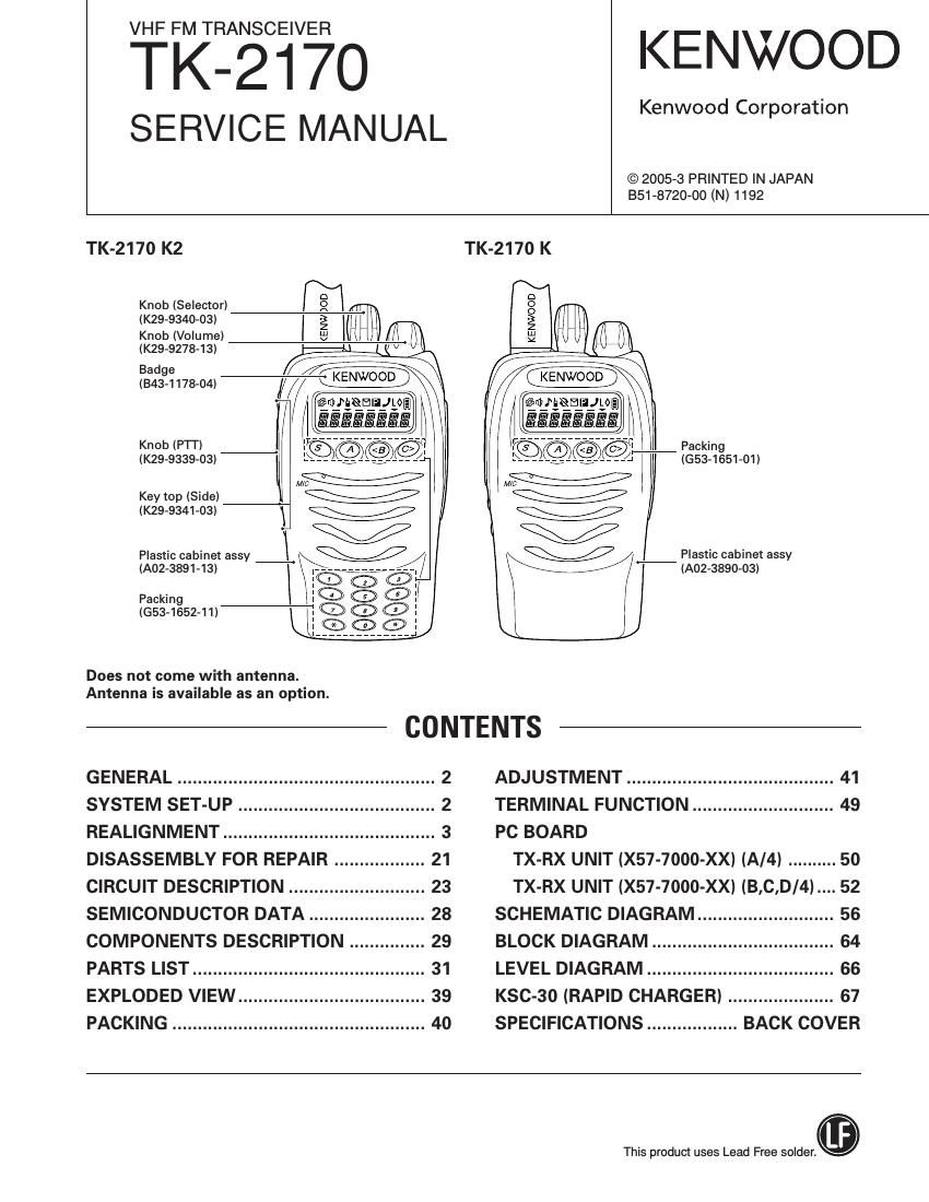
TK-2170 K2
D
KnobISelector) m i
(K29-9340-03) ; (m
Knob (Volume) 9%
(K294327843)


(Saginaw-7f @

4EEWMREIIJLOQ]
l


Knob IP'I'I')
(K29-9339-03I

Key top (Side)
(K29-934I -03I

Plastic cabinet assy
(A02-3891-13) _______________
Packing

(653-1652-11)

_______________

Does not come with antenna.
Antenna is available as an option.

TK-2170 K

.i KENWOOD

Packing
((353-1651-01)

Plastic cabinet assy
IA02-3890-03)

CONTENTS

GENERAL ................................................... 2 ADJUSTMENT ......................................... 41
SYSTEM SET-UP ....................................... 2 TERMINAL FUNCTION ............................ 49
REALIGNMENT .......................................... 3 PC BOARD

DISASSEMBLY FOR REPAIR 21 TX-RX UNIT (X57-7000-XXI IA/4I .......... 50
CIRCUIT DESCRIPTION ........................... 23 TX-RX UNIT (X57-7000-XXI (B,C,D/4I.... 52
SEMICONDUCTOR DATA ....................... 28 SCHEMATIC DIAGRAM ........................... 56
COMPONENTS DESCRIPTION ............... 29 BLOCK DIAGRAM .................................... 64
PARTS LIST .............................................. 31 LEVEL DIAGRAM ..................................... 66
EXPLODED VIEW ..................................... 39 KSC-30 (RAPID CHARGER) ..................... 67
PACKING .................................................. 40 SPECIFICATIONS .................. BACK COVER

This produa uses Lead Free solder..

Page 2

TK-217O

GENERAL/SYSTEM SET-UP

INTRODUCTION PERSONAL SAFETY
SCOPE OF THIS MANUAL The following precautions are recommended for person-
This manual is intended for use by experienced techniA nel safety:
cians familiar with similar types of commercial grade commu- DO NOT transmit until all RF connectors are verified see
nications equipment. It contains all required service informa- cure and any open connectors are properly terminated.
tion for the equipment and is current as of the publication 0 SHUT OFF and DO NOT operate this equipment near elec»
date. Changes which may occur after publication are covered trical blasting caps or ln an explosive atmosphere.
by either Service Bulletins or Manual Revisions. These are 0 This equipment should be serviced by a qualified techni-
issued as required. cian only.
ORDERING REPLACEMENT PARTS SERVICE
When Ordering replacement parts or equipment informa- This radio is designed for easy servicing. Refer to the
tion, the full part identification number should be included. schematic diagrams, printed CerUit board views, and align,
This applies to all parts : components, kits, or chassis. If the ment procedures Contained within.

part number is not known, include the chassis or kit number
of which it is a part, and a sufficient description of the re
qulred component for proper identification.

SYSTEM SE T-UP

License and frequency allocated by FCC

I Frequency range (MHZ) RF power Type
C Choose the type of transceiver )-> TX/RX136~174 5w TK-2170 K,K2

( Transceiver programming ) A personal computer (IBM PC or compatible), programming

interface lKPG-22), and programming software lKPG-1OTD)
are required for programming.

(The frequency, TX power HI/LOW, and signaling data are
programmed for the transceiver.)

YES
( Are you using the optional antenna? )-> KRA»22 or KRA-ZG

NO Optional antenna

(Option)
. . YES
( Are you usmg the speaker mrcrophone? )-> KMC-17 or KMC-21

NO Speaker microphone

(Option)
I Delivery )

Page 5

TK-217O

REALIGNMENT

How to enter the password with the selector;

lf the selector is rotated while "CLN LOCK" is displayed,
numbers (0 to 9) are displayed flashing. When you press
the [C] key, the currently selected number is determined.
It you press the [8] key after entering the password in this
procedure, "CLONE" is displayed if the entered password
is correct. If the password is incorrect, CLN LOCK is
redisplayed.

4. Power on the slave transceiver.

5. Connect the cloning cable (part No. E30-3410705) to the
SP/MlC connectors on the master and slave.

6. Press the [8] key on the master while the master displays
"CLONE". The data of the master is sent to the slave.
While the slave is receiving the data, PROGRAM" is dis-
played. When cloning of data is completed, the master
displays "END", and the slave automatically operates in
the User mode. The slave can then be operated by the
same program as the master.

7. The other slave can be continuously cloned. When the [S]
key on the master is pressed while the master displays
"END", the master displays "CLONE". Carry out the op-
eration in step 4 to 6.

Notes:
Cannot be cloned if the password (over write password) is
programmed to the slave.
Only the same models can be cloned together.

Cloning cable
(E30-3410-05)

Fig. 2

8. Self-Programming Mode

This mode allows you to write the frequency data and sig
naling, etc. to the equipment. This mode is to be used ONLY
by authorized service personnel who are maintaining the
user's equipment. After programming, reset the FPU to dis
able SelfA Programming" mode. Radios CANNOT be delivl
ered to the end-user with self-programming mode enabled.

8-1. Entering Self-Programming Mode
Remove D14 on the control unit (X57 B/4) first.
1. Press and hold the [C] key for 2 seconds while turning the
power on.
2. When selfaprogramming mode is enabled, " SELF " apA
pears on the display.

TX-RX UNIT (3/4)

Foil side

8-2. Adding a Data Password

If a data password is set in the optional feature menu, you
must enter the password to activate selprrogramming
mode.

The password can consist of 6 digits, ranging from O~9.

I To enter the password using the keypad:

1. Press a key while "SLF.LOCK.R" or SLF.LOCK.W" is
displayed. The number that was pressed will appear on
the display.

2. Each press of the key shifts the display in order to the left.

3. When you have entered the entire password, press the
[-x-] or [8] key. SELF" appears on the display if the en-
tered password is correct. If the password is incorrect,
SLF.LOCK.R" or SLF.LOCK.W" is redisplayed.

I To enter the password using the selector:

1. Rotate the selector while "SLF.LOCK.R" or SLF.LOCK.
W" is displayed. A number (0 to 9) will appear on the
display and flash.

2. Press the [C] key. The currently selected number is set.

3. When you have entered the entire password, press the [8]
key. SELF" appears on the display if the entered passe
word is correct. If the password is incorrect, SLF.LOCK.
R" or "SLF.LOCK.W" is redisplayed.

Note:
- Self-programming mode cannot be set when it has been
disabled by the FPU.

[C + Power on]

Self»programming mode

[Sidel] [Side2]

Function setting Channel select [A] Zone select
mode mode mode
l [C] l [C]
Channel edit Zone edit
mode mode

Page 27

TK-217O

CIRCUIT DESCRIPTION

|C13
AQUA-L

ICl7 (1/2)

BUFF
AMP TCXO

ICI4

HSDO 4 , t, .l. ér-Vfil.:?SIElMW__

l RX Audio

EI-IF

ICIZ 08 I8
MOD MOD

6 I AMP I2 02

-l§-Vll -> [gm-93+» AMP

$.23
RXAF l_£}_____04
3O
LSDO vvrl vvr-L
Fig. 12 Encode

6-2. Decode
I QT/DQT

The output signal from IF IC (IC701) enters the microproa
cessor (IC7) through lCi 1. |C7 determines whether the OT
or DOT matches the preset value, and controls the AMl us,
ing |C5 and the speaker output sounds according to the
squelch results.

I Z-tone

Part of the received AF signal output from the AF amplifier
lCiO, and then passes through an audio processor (IC13),
goes to the other AF amplifier |C15, is compared, and then
goes to IC7. |C7 checks whether 2~tone data is necessaw. If
it matches, |C7 carries out a specified operation, such as turna
ing the speaker on. (See Figure 4)

I MSK (Fleet Sync)

Fleet Sync utilizes iZOObps and 2400bps MSK signal is
output from pin 6 of lCl 3. And is routed to the VCO. When
encoding MSK, the microphone input signal is muted.

I DTMF

The DTMF input signal from the IF IC (lC70i) is amplified
by lCiO and goes to [Cl 3. The decoded information is then
processed by the CPU.

7. Power Supply

There are five 5V power supplies for the microprocessor:
5M, 5M8, 5C, BR and 5T.

SM is always output while the power is on. 5M is always
output, but turns off when the power is turned off to prevent
malfunction of the microprocessor.

5C is a common 5V and is output when SAVE is not set to
OFF.

SR is 5V for reception and output during reception.

ST is 5V for transmission and output during transmission.

27