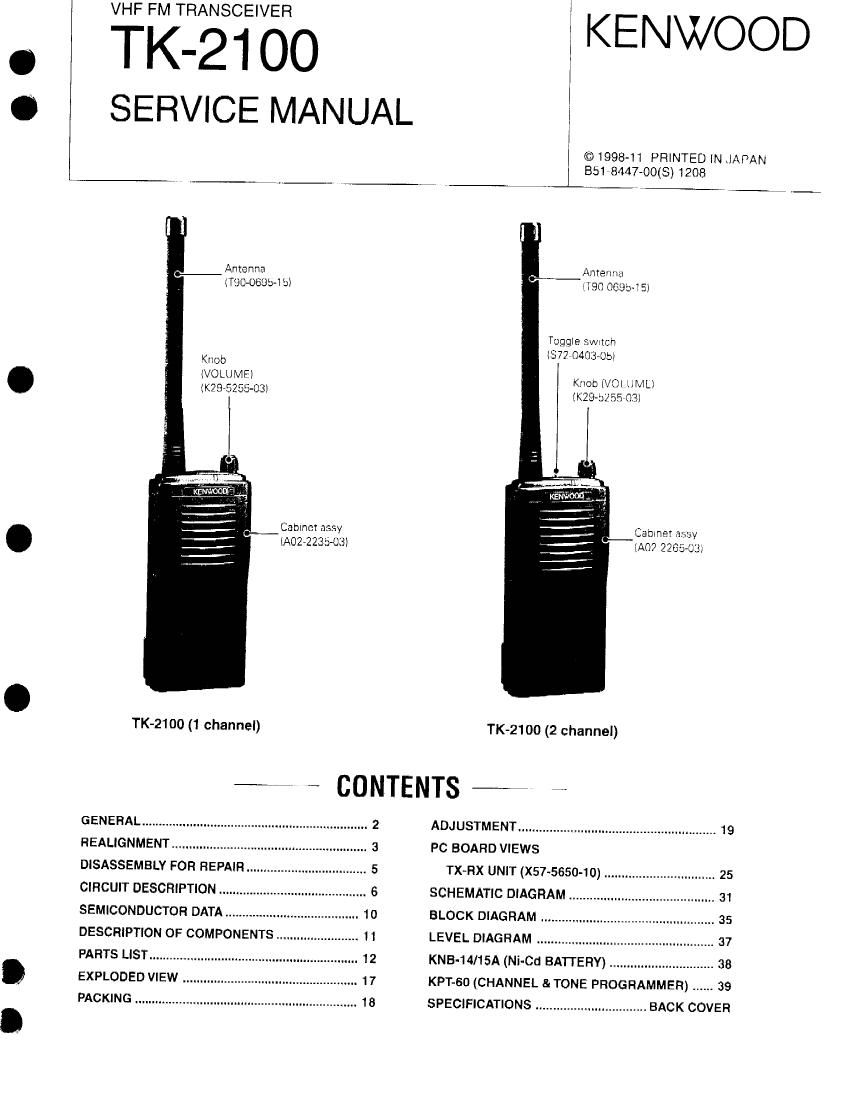
Kenwood TK 2100 Service Manual

This is the 40 pages manual for Kenwood TK 2100 Service Manual.
Read or download the pdf for free. If you want to contribute, please mail your pdfs to info@audioservicemanuals.com.

Page: 1 / 40
left right
Kenwood TK 2100 Service Manual

Extracted text from Kenwood TK 2100 Service Manual (Ocr-read)


Page 1

VHF FM TRANSCEIVER

©1998-11 PRINTED IN JAPAN

J
I
SERVICE MANUAL I
I

851 8447-00(S) 1208


Antenna
(Tim-06854 b)

.-

Knob
(VOLUME)
IK2975255-03I

Cabmct assy
(Am-223.5413)

TK-21OO (1 channel)

_ Antenna
{T90 0695- S)

Toggte r'MnCh
I377 0403-05)

Knot) (V0 LU MLI
(K2932 55 03)

Cabinet assy
{A07 2265-03)

TK-2100 (2 channel)

L ~ CONTENTS _, ~

GENERAL...
REALIGNMENT.

. 2

..... 5

DISASSEMELY FOR REPAIR .......................

CIRCUIT DESCRIPTION ........................................... 6
SEMICONDUCTOR DATA ............... 10
DESCRIPTION OF COMPONENTS V. 11
PARTS LIST ..................................... .. 12
EXPLODED VIEW ................................................... 17
PACKING ................................................................. 18

ADJUSTMENT ......................................................... 19
PC BOARD VIEWS

TX-RX UNIT (X57-5650-10) 25

SCHEMATIC DIAGRAM ............. . 31
BLOCK DIAGRAM ........................... 35
LEVEL DIAGRAM ................................................... 37
KNB-14/15A (Ni-Cd BATTERY) .............................. 38
KPT-SD (CHANNEL &TONE PROGRAMMER) ...... 39
SPECIFICATIONS ................................ BACK COVER

Page 2

-TT(-21 00

GENERAL

INTRODUCTION

SCOPE OF THIS MANUAL

This manual is intended for use by experienced technicians
familiar with similar types of commercial grade communications
equipment. it contains all required service information for the
equipment and is current as of the publication date. Changes
which may occur after publication are covered by either Service
Bulletins or Manual Revisions. These are issued as required.

ORDERING REPLACEMENT PARTS

When ordering replacement parts or equipment information,
the full part identification number should be included. This applies
to all parts : components, kits, or chassis. It the part number IS not
known. include the chassis or kit number of which it is a part, and
a sufficient description of the required component for proper
identification.

PERSONNEL SAFETY
The tollowrng precautions are recommended for personnel

safety :

- DO NOT transmit until all FlF connectors are verified secure
and any open connectors are properly terminated.

0 SHUT OFF and DO NOT operate this equipment near
electrical blasting caps or in an explosive atmosphere.

- This equipment should be serviced by a qualified technician
only.

SERVICE

This radio is designed for easy servicing. Fieler to the
schematic diagrams, printed circuit board views, and alignment
procedures contained within.

NOTE

WE CANNOT guarantee oscillator stability when using
channel element manufactured by other than KENWOOD or its
authorized agents.

TK-2100
Destination number of CH Frequency NuJFrequency Color Factory default CH setting HF power output
K 1channe| i54.5700MHZ/QT 67.0HZ
Color I Blue
1 151.6250MHZ Red
2 151 .9550MH2 Purple -,.. . . . 2W
3 154'5700MH2 Ema CH1 . 154.5700MHz/or 67.on
4 154.6000MHZ Green .
Color : Blue
K2 2 channel
CH2: 154.6000MHZ/OT 67.0Hz
Color: Green