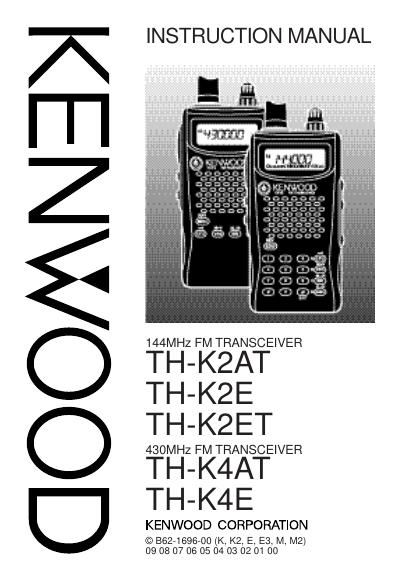
Kenwood THK 2 Owners Manual

This is the 154 pages manual for Kenwood THK 2 Owners Manual.
Read or download the pdf for free. If you want to contribute, please mail your pdfs to info@audioservicemanuals.com.

Page: 1 / 154
left right
Kenwood THK 2 Owners Manual

Extracted text from Kenwood THK 2 Owners Manual (Ocr-read)


Page 1

NOTICE TO THE U SER One or more of the following statements may be applicable for this equipment. FCC WARNING This equipment generates or uses radio frequency energy. Changes or modifications to this equipment may cause harmful interference unless the modifications are expressly approved in the instruction manual. The user could lose the authority to operate this equipment if an unauthorized change or modification is made. INFORMATION TO THE DIGITAL DEVICE USER REQUIRED BY THE FCC This equipment has been tested and found to comply with the limits for a Class B digital device, pursuant to Part 15 of the FCC Rules. These limits are designed to provide reasonable protection against harmful interference in a residential installation. This equipment generates, uses and can generate radio frequency energy and, if not installed and used in accordance with the instructions, may cause harmful interference to radio communications. However, there is no guarantee that the interference will not occur in a particular installation. If this equipment does cause harmful interference to radio or television reception, which can be determined by turning the equipment off and on, the user is encouraged to try to correct the interference by one or more of the following measures: ¥ Reorient or relocate the receiving antenna. ¥ Increase the separation between the equipment and receiver. ¥ Connect the equipment to an outlet on a circuit different from that to which the receiver is connected. ¥ Consult the dealer for technical assistance.

Page 2

MODELS COVERED BY THIS M ANUAL The models listed below are covered by this manual. TH-K2AT, TH-K2E, TH-K2ET TH-K4AT, TH-K4E MARKET CODES Kn: The Americas En: Europe Mn: General (Where n represents a variation number.) The market code is printed on the bar-code label of the carton box. Refer to the product specifications {pages 122 ~ 133} for information on the available operating frequencies within each model. For accessories supplied with each model, refer to pages vii ~ ix.

Page 42

29 e h t n O y a l p s i D u n e M . o N s n o i t c e l e S t l u a f e D . f e R e g a P O P A71.n i m 0 8 1 / 0 2 1 / 0 9 / 0 6 / 0 3 / F F O0328 O R A 2 9FF O / N ONO73 L C B42FF O / N OFF O68 P B72FF O / N ONO58 S B82FF O / N OFF O58 K C 1 8 105 7 1 / L L A C/ L L A C 0 5 7 1, 6 3 4 6 T C4 zH 1 . 4 5 2 ~ 0 . 7 65. 8 807 S C D545 7 ~ 3 2 032 047 R M . F M T D23st i g i d 6 1 o t p UÐ77 H . T D 3 4 3FF O / N OFF O77 L . T D63FF O / N OFF O18 C N E03FF O / N OFF O98 N M F92FF O / N OFF O19 D L H91FF O / N OFF O63 T U O . L21FF O / N OFF O76 H C . M3100 1 / 0 50514 F D M51QR F / N MNM94 E M A N . M41sr e t c a r a h c 6Ð84 T E S F F O 1 8f o s p e t s n i z H M 0 5 9 . 9 6 ~ 0 0 0 . 0 z H k 0 5/ 0 0 6 . 0 / 0 0 6 . 1 0 0 0 . 53 3 A P53/ 0 0 5 1 / 0 0 0 1 / 0 5 7 / 0 0 5 / 0 5 2 / 0 0 1 s m 0 0 0 20 0 508 C P13FF O / N OFF O70 1 G S M . N O . P62sr e t c a r a h c 6Ð29 ALPHABETICAL FUNCTION LIST

Page 46

33 1Press [MENU]. 2Turn the Tuning control to select Menu No. 6 (SFT). 3Press [MENU]. 4Turn the Tuning control to select Ò+Ó or ÒÐÓ. ¥ To program a Ð7.6 MHz offset (TH-K4E only), select ÒÐ7.6Ó instead. 5Press [MENU] to store the setting or [PTT] to cancel. ¥ Ò+Ó or ÒÐÓ (or Ò Ó) appears above the frequency, indicating which offset direction is selected. If the offset transmission frequency falls outside the allowable range, transmission is inhibited. In this case, adjust the reception frequency so that the transmission frequency is within the band limits. Note: While using an odd-split memory channel or transmitting,you cannot change the offset direction. n Selecting an Offset Frequency To access a repeater which requires an odd-split frequency pair, change the offset frequency from the default which is used by most repeaters. The default offset frequency on the 2 m band is 600 kHz (all TH-K2 models); the default on the 70 cm band is 5.0 MHz (TH-K4AT) or 1.6 MHz (TH-K4E).

Page 92

79 Transmitting a Stored DTMF Number 1While pressing and holding [PTT], press [MENU]. 2Release [MENU] (continue pressing [PTT]), then turn the Tuning control to select the desired DTMF memory channel number. 3While still holding [PTT], press [MENU] again to transmit the selected DTMF tones. ¥ The number stored in the channel scrolls across the display, accompanied by DTMF tones from the speaker. ¥ After transmission, the frequency display is restored. TH-K2AT/ ET/ K4AT only: If you do not need to confirm the memory channel contents, press [0] ~ [9] instead of turning the Tuning control in step 2, to select a channel number. The stored DTMF number will be immediately transmitted. (You do not have to press [MENU] in step 3.) Note: If you select an empty DTMF memory channel and press[MENU], the frequency display is restored.

Page 105

92 When narrow band FM operation is ON, ÒNÓ appears in the top right of the LCD. Note: You can store the narrow band FM operation status to thememory channels {page 41}. POWER -ON M ESSAGE You can change the Power-ON Message (a maximum of 6 characters) when the transceiver is turned ON. 1Press [MENU]. 2Turn the Tuning control to select Menu No. 26 (P.ON.MSG). 3Press [MENU]. ¥ The current message and entry cursor appear. ¥ The cursor moves to the next digit. 4Turn the Tuning control to select a character. ¥ You can enter the following alphanumeric characters: 0 ~ 9, A ~ Z, Ð (hyphen), / (slash) and a space. 5Press [MENU]. ¥ The cursor moves to the next digit. 6Repeat steps 4 and 5 to enter up to 6 digits.

Page 111

98 ¥ If the transmission does not begin, you must readjust the VOX Gain so that transeiver transmits while you are speaking. To readjust the gain, press and hold [PTT] then turn the Tuning control to select a more sensitive gain level. ¥ While readjusting the gain, you can release [PTT]. The transceiver will remain in Adjustment Mode for approximately 5 seconds. 3Adjust the VOX Gain by turning the Tuning control until the transceiver reliably switches to transmission mode each time you speak while the transceiver is transmitting. From the Menu: 1Continue from step 1 and 2 from VOX (Voice- Operated Trasmission) on page 97. 2Press [MENU] to store the VOX Gain level. ¥ÒVOXÓ appears on the bottom right of the display when the VOX function is ON. 3Press any key other than [LAMP], [MONI/SQL] and [MENU] to exit Menu Mode. 4Adjust the VOX Gain, performing steps 1 to 3 until the transceiver reliably switches between transmission and reception each time you speak. ¥ The setting should not allow background noise to switch the transceiver to Transmission Mode.

Page 118

105 Note 1: Voltage is developed across a 100W resistor on the 5 V line in the transceiver. When 2 mA flows, approximately 4.8 V is developed. Note 2: A 10 mF capacitor is not required in the following cases: ¥ When other equipment has DC blocking capacitors. ¥ When a 2-terminal electret condenser microphone is used. PC To connect the transceiver to a PC in order to manage the memory channels in the transceiver, use the PG-4Y PC interface cable. You will also need the supported software to manage the memory channel contents of the transceiver. To download the software, access the following URL: http://www .kenwood.com/i/products/info/amateur .htm. To use the software, access Menu No. 31 and select ÒONÓ {page 107}. For your reference, the following diagram shows how the transceiver communicates to the PC using a serial (COM) port. RXD DTR DSR GND RTS CTS TXD SP MIC Note: Contact an authorized KENWOOD dealer for the PG-4Y, PCInterface cable availability. 2.5 mm Plug SP/MIC jackLevel converter COM port 3.5 mm Plug

Page 148

135 Clearing Memory Channel.................................................... 47 COM Port................................................................... 106 CT (Menu No. 4).......................................................... 70 CTCSS Freq. ID Scan.......................................................... 72 Selecting a, Frequency........................................... 70 Using...................................................................... 69 D DC IN jack........................................................ 6, 12, 115 DCS (Menu No. 5) Code ID Scan......................................................... 75 Selecting a, Code.................................................... 74 Using...................................................................... 73 Direct Frequency Entry................................................ 21 Display LCD ........................................................................ 14 DT.H (Menu No. 34)..................................................... 77 DT.L (Menu No. 36)...................................................... 81 DTMF Adjusting the Pause Duration.................................. 80 Adjusting the, Tone Transmission Speed................. 80 Automatic Dialer...................................................... 77 Key Lock................................................................. 81 Manual Dialing........................................................ 76 Storing a, Number in memory................................. 77 Transmitting a Stored, Number................................ 79 TX hold................................................................... 77 DTMF.MR (Menu No. 32)............................................. 77 E ENC (Menu No. 30)..................................................... 89 F First QSO..................................................................... 10 FMN (Menu No. 29)..................................................... 91