Kenwood SM 230 Service Manual

This is the 43 pages manual for Kenwood SM 230 Service Manual.
Read or download the pdf for free. If you want to contribute, please mail your pdfs to info@audioservicemanuals.com.

Page: 1 / 43
left right
Kenwood SM 230 Service Manual

Extracted text from Kenwood SM 230 Service Manual (Ocr-read)


Page 1

SM-230 KENWOOD
SERVICE MANUAL

©1989-9 PRINTED IN JAPAN
851-8027-OO(T)899

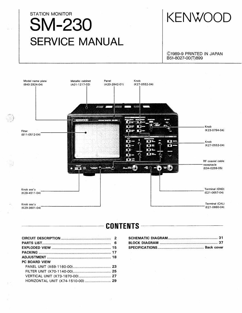
Model name plate Metallic cabinet Panel Knob
IAO1-12I7»02I IA202842-01I IK27-0552-04I

I340» 2 9 24-04)

Knob
Filter (K23v0794-04)
IBI 1-0512-04I
Knob
(K27-0553-04)
RF coaxial cable
recepmcle
(E04v0259-05I
Knob assy Terminal IGND)
(294511-041 IE21-0657-O4I
Knob assv Terminal (CALI
(K29-3601-04I (E21-0660»04I
CIRCUIT DESCRIPTION ............ SCHEMATIC DIAGRAM
PARTS LIST ............................ BLOCK DIAGRAM
EXPLODED VIEW SPECIFICATIONS ......................... Back cover
PACKING ........
ADJUSTMENT .

PC BOARD VIEW
PANEL UNIT (X69-1160-00I .............
FILTER UNIT (X70-1140«00I ........
VERTICAL UNIT (X73-1870-OOI
HORIZONTAL UNIT (X741510-00I .

Page 2

SM-230

CIRCUIT DESCRIPTION

0 Oscilloscope input circuit and preamplifier
(X57-1870-00)

When the unit is used as an oscilloscope, the input signal ap-
plied to the INPUT BNC socket on the panel is input to the ver»
tical power supply unit (X73-1870-00). The signal passes
through the input signal ground circuit, consisting of an AC-
DC switching circuit with relays K1 and K2, and is input to the
attenuation circuit,

VIN

moo l/ID AMP
l 0- A1"! -0 0- ATT -0

till)
ill
on
AC 3 K4

K2

K1 , .
Figure 1

The attenuation circuit has two attenuators connected in ser-
ies, each with two attenuation ratios. The first attenuator
switches between 1/1 and 1/100, and supplies - 10 V to the
relay only when the ratio is 1/100. The second attenuator
switches between 1/1 and 1/10, and supplies - 10 V to the
relay only when the ratio is 1/10.

After the signal has passed through the attenuation circuit, it
is applied to the source follwer of Uta. Ul is a constant cur-
rent load source follower with a dual FET to reduce the DC off-
set and temperature drift. 01 is connected to a diode to protect
against large negative amplitudes. The signal output from the
source follower is attenuated by the vertical potentiometer on
the panel and input to the preamplifier, consisting of 02, 03,
05, and U2b, where 02 is an emitter followert The high fre-
quency component is amplified by 03 and the low frequency
component is amplified by U2b (feed forward configuration).
The signal is output to the final amplifier of the horizontal unit
(X74-1510-00) via 05. U2a used for a band scope, receives
signals from the logarithmic amplifier of the horizontal unit.
Since relay K2 is forcibly grounded at this time, signals input
to the oscilloscope are not transferred to the preamplifier.

O Constant-voltage stabilizing circuit
(X73-1870-00)
The stabilizing power supply produces +5 V, :10 V, and
+ 140 V. Each supply consists of an operational amplifier and
control transistor, The :10 V supply is generated from non-
stabilized 13 V, +140 V is generated from non-stabilized
170 V, and + 5 V is generated from non-stabilized +10 V, For
:10 V and + 140 V, bleeder resistors R101. R107, and R117
are connected in parallel to reduce the power consumption of
the control transistors,

R101
010:
>_~ + A Tlsov
acmv + .,.
" if if
1! . UlOlu
oroz '
J,
5107
orbs
>_., 4, NOV
AC|3V + +
>_.-. __
i uroz
0,04 urom '
We,
-:
:>
' +5v
%
/
.__Jw,._
0:05
-iov
E
a
; +

Figure 2

Page 19

1-

ADJUSTMENT

SM-230

Measurement Adjustment
It T t
em Condition ,1 Specification/Remarks
equip- Termlv
ment Unit nal Unit Port Method
B. FOCUS FUNCTION: X-TUNE Scope Vertical Vertical VRISI Adjust the ASTIG VFI on Exact focusing should be
FOCUS VR: Center face power power the from panel and VB obtained in 9 oclock to 3
supply supply 151 so that the spot is oclock position of the
unit unit minimized. FOCUS VR.

9. Luminesce- FUNCTION: OSCILLOSCOPE VR152 Adjust to a point at Rotating the INTENSITY
nt line dis» INTENSITY VR: 9 oclock position which the spot dis~ VR, the spot should be dis»
appearance appears. appear in 8 oclock to 10
point o'clock position.

10. SWEEP FUNCTION: OSCILLOSCOPE Horizo- Horizo~ VH1 Adjust so that a wave of i 5%

TIME SWEEP RANGE: 100 to 1 kHz, 0 nt el n tel 10 cycles appears on the
unit unit scope face.
HorizontaI VARIABLE VR: Clockwise va-L:
MAX ®
INPUT: 10 kHz, square wave
11. Vertical FUNCTION: OSCILLOSCOPE VR101 Adjust to 5 divisions on
sensitivity ATTENUATION: 1 A the scale on the scope
C) face.
Vertical VARIABLE VR: Clockwise
MAX VfiLE
INPUT: 1 kHz. 50 mV
12. TWO» (D Set the VHS on the panel unit to its AF VM Pin 7 of » VH301 3.87 V
TONE mechanical center. U301
output 1575 Hz tone switch: ON 9 qp
o 2 ,
® 1000 Hz tone switch: ON 0 : Jim Pin 1 of VR302
a 9 U301
® 1575 Hz and 1000 Hz tone BNC VR303 5 mV £2036
switches: ON con-
nectar
of
TONE
OUT

13. Space FUNCTION: X~TUNE Scope V3304 Adjust to the center of :1 div

position Input: None face the 50098 face.

14. Mark FUNCTION: XvTUNE V3306

position Input: None

19

<
\

Page 33

_
_
_
_
_
_
_
_
_
_
_
_
_
_
_
_
_
_
_
_
_
_
_
r

m
o
.

m
H.
.

u
x
T
N
u
L
A
T
M
0
u
a
o
M

m

.2 :2

... E.

.1 g:

...
a. m
«Gun

34

33

Page 34

_
_
_
_
_
_
_
_
_
_
_
_
_
_
_
_
_
_
_
_
_
_
_
r

m
o
.

m
H.
.

u
x
T
N
u
L
A
T
M
0
u
a
o
M

m

.2 :2

... E.

.1 g:

...
a. m
«Gun

34

33

Page 42

KENWOOD

SERVICE BULLETIN AMATEUR RADIO

SUBJECT DATE
SM-23O RTTY CROSS PATTERN ATTENUATION 08/08/90

Some users of the SM-23O have reported that the MARK and SPACE gain
adjustments do not sufficiently reduce the signals to display them on the
CRT. The following modification will correct this condition.

REQUIRED PARTS :

680 OHM l/8W RESISTOR RD14CBZB681J QTY. 2

1. Disconnect the power cord and control cables.
2. Remove the top cover (6 screws).

3. Locate the Horizontal unit. This board is vertically mounted on the
right side of the SM-230.

4. Locate resistors R318 and R322 on the Horizontal unit.
5. Replace R318 and R322 with 680 ohm resistors.
6. Assemble the SM-230.

7. Adjust the MARK and SPACE gain adjustments as necessary to obtain the
correct cross pattern.

GD NHRK SPHCE
GRIN GRIN R318

R322 ~00<é @5on @

<86
II

HHRK SPHCE
P03. P08.

Time required to perform this modification is 1 hr. or less.
Copyright (C)073190EWP for Kenwood U.S.A. Corporation.

KENWOOD U.S.A. CORPORATION 2201 EAST DOMINGUEZ STREET . LONG BEACH, CALIFORNIA 90310
MAILING: 9.0. BOX 22745 . LONG BEACH. CALIFORNIA 908016745
TELEPHONE: I213I 5309000