Kenwood SE 7 Service Manual

This is the 27 pages manual for Kenwood SE 7 Service Manual.
Read or download the pdf for free. If you want to contribute, please mail your pdfs to info@audioservicemanuals.com.

Page: 1 / 27
left right
Kenwood SE 7 Service Manual

Extracted text from Kenwood SE 7 Service Manual (Ocr-read)


Page 1

Rrsm/sar'uc) (K) COVER(97tll.280122AM y [w 2 :r
K

R-SE7/SE-7(G KENWOOD

SERVICE MANUAL
(HM-701)

©1997-10/851-5373-00 (K/K) 3191

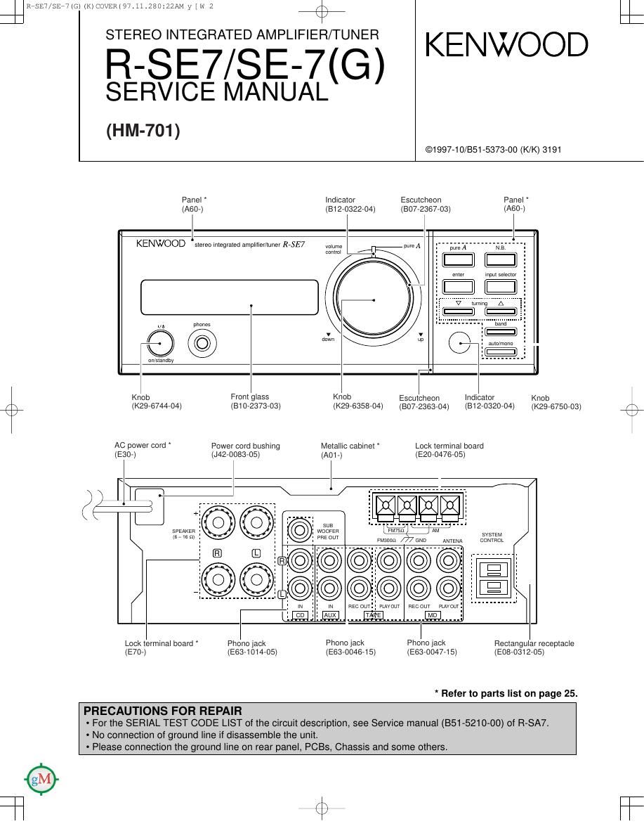
Panel Indicator Escutcheon Panel
(A60-) (812-0322-04) (807-2367-03) (A60-)

KENWOOD stereo integrated amplifier/tuner RVSE7

volume pure A I pure A NE,

comm -. IE [E]

p my .
phones

V V

l/U) .
Q down p O I :
: auto/mono ,

arr/standby


H

Knob From glass Knob Escutcheon Indicator Knob

(K29-6744-04) (310-2373-03) (K296358434) (807-2363-04) (312-0320-04) (K29-6750-03) (3
AC power cord Power cord bushing Metallic cabinet * Lock terminal board
(E30-) (J42-0083-05) (A01-) (E20-0476-05)

SPEAKER
(6 7 6 Sll SYSTEM

CONTROL

LE.

Lock terminal board Phonojack Phone Jack Pnono jack Rectangular receptacle
(E70-) (E83-1014-05) (E63-0046-15) (Em-00474 5) (E08-0312-05)

* Refer to parts list on page 25.

PRECAUTIONS FOR REPAIR

- For the SERIAL TEST CODE LIST of the circuit description, see Service manual (851-5210-00) of R»SA7.
- No connection of ground line if disassemble the unit.

- Please connection the ground line on rear panel, PCBs, Chassis and some others.

Page 2

Ram/5124(6) (K) COVER(97tll.280122AM y [w 3

R-SE7/SE-7(G)
c

%

ONTENTS / ACCESSORIES

Contents

CONTENTS / ACCESSORIES
CIRCUIT DESCRIPTION ......

o'oo'com

EXPLODED VIEW

SCHEMATIC DIAGRAM

ADJUSTMENT ..... PARTS LIST ............... 25
PC BOARD .......... SPECIFICATIONS ........... Back cover
Accessories

I N

..__. AM loop antenna (1) ..........................................
T - 82 -
I 90 0 0 05) AM loop antenna stand (1)
(J19-3645-05)

Remote control Unit (1)
(A70-1154-05) : KM
(A70-1155-05) : TE

FM indoor antenna (1)
(T90-0182-15) : KM
(T90-0806-05) : ET


\\ \ /
Audio cords (2) System control cord (1)
(E30-0615-05) (E30-2628-05)

Battery cover (A09-0374-08)

D
8
B
Z
LIJ
x

VOLUME
CONTROL

BEECH;

NE. MUTE

INPUT

REMOTE CONTROL UNIT

Batteries (RS/AA) (2)

System configuration

SYSTEM NAME AMP/TUNER CD PLAYER SPEAKER

HM-701 R-SE7 DP-SE7 LS-SE7

Page 14

CIR/ADJ 97.11t283131AM y [w 6

P R T
TUNER UNIT (X05-4622-71) :TE
é?
D61
J | 052 A1 FM FRONT END(W02-2565-05)
AM ANT 0- -
J20 DISTORTION (ST) W 5
GND 0 _I ml
1 is
ca M TR2 .--. 01: I
. . .1 1
FM 759 ( ) I I E m g I
i 25% - as 3 z 3
I WI I I N % 99v
019
4
2 , mo
N 5 R7 mm
o , o.
J2 $é ax In 100K g =
c9 I: 012 TR4 g
2P l2P 7 0
_.
m u. K'S
| ., 1%. D2 6*;
TR1 .ZSK360 0,7 4 1 I g l ,
I TR2 .280262008 00 l: ale 3
I TR3~5 .ZSCZAIBKorZSCZWB :m 6::
D1~3 .1sv225 or HVM16 I"
|_
101 .LA1035
WVWAGE Ic2 . Lc72131
LF LDWFREOUENCV ICE . MSZZBFP
HF H/GHFHEOUENCY
BAND FREQ VOLTAGEyl/T) 01.2 2302714419)
L; N 03.81 103 .2SA1585(V,GR)or2SA1611 W 031.32 .23011151chor2sc4177(L5,Le)
HF 75v 0101 102 .2so1757K
W L V D133 5162 :1ss133 or Hss104
H; 4 5V D31 : MTZJB 2(5) or UZ-BZBSB
D32 .MA111
D81 .MTZJS 1(5) or uz;5.1Bsa
D101 .MTZJ3 3(5) or uzr3,3Bsa

CAUTION: For continued safety, replace safety critical components only with manu-
facturer's recommended parts (refer to parts list). A indicates safety critical compo-
nents. For continued protection against risk of fire, replace only with same type and
rating fuse(s). To reduce the risk of electric shock, leakage-current or resistance
measurements shall be carried out (exposed parts are acceptably insulated from
the supply circuit) before the appliance is returned to the customer.

The DC voltage is an actual reading measured with a high impedance type volt-
meter as the AM/FM signal generator is specified to the conditions as shown in the
list below. The measurement value may vary depending on the measuring instru-
ments used or on the product. The value shown in ( ) is actual reading measured
in the AM made.

MODULATION
MODE CARRIER ANT INPUT
FREQUENCY DEVIATION
FM 98MHZ 1kHZ STEREO 67.5kHZ 7.5kHZ(Pilot) 60dB
AM 1000(999)kHz 400HZ MONO 30% MOD 60dB

SIGNAL LINE
GND LlNE