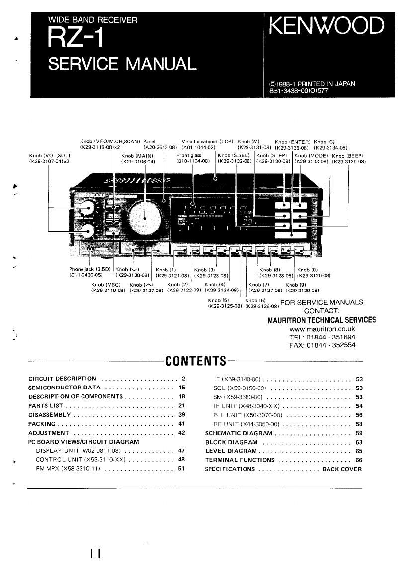
Kenwood RZ 1 Service Manual

This is the 72 pages manual for Kenwood RZ 1 Service Manual.
Read or download the pdf for free. If you want to contribute, please mail your pdfs to info@audioservicemanuals.com.

Page: 1 / 72
left right
Kenwood RZ 1 Service Manual

Extracted text from Kenwood RZ 1 Service Manual (Ocr-read)


Page 2

RZ-I

CIRCUIT DESCRIPTION 7"

GENERAL

The RZ-l is equtpped with a digital VFO capable of tunA
ing EOOkl-lz to 905MH7 M, W, EOOkl-lz to 824MHz K in
5kHz. 12.6kHz, and 20 or ZSkHz steps. It IS capable or
receiving in the AM, FM-Narrow and FlVI-Wide modes.
Additionally the Auto Mode wali automatically select the
proper mode for those frequency bands in which the mode
/cnanne| steps are fixed. such as the broadcast bands, etc.

in the FMeWide mode the unit Is capable of receiving
stereophonic broadcasts. An output terminal is provided
so that the unit can be easily Integrated with our home
audio component stereo equipment A terminal is also
provided to allow connection to a television monitor for
video Signal reception. The major features of this unit are;

In 20d 3rd 15: 2nd 3rd
kHZ Zone Zone Zone MHZ Zone Zone Zone
10 100
525 10,150
11 .650
12,050
1506 13.600
1705 13300
H.000
30° 14.350
2000
15.000
2300 15.100
250° 15.600
3200 17.550
17.900
3000
3500 18.068
13.150
38" 20.000
23:: 21.000
21.450
21.850
4750
24.590
24.330
5000 25,000
6060 25.670

26.100

595° 28.000

29.700
6200

7000
7100
7300

9500
47 ,000

9900
1 0000

50 .000

0

Continuous reception from BOOkHz to 905MHz M, W,
500kl Iz to 824MHz K.

100 Memory Channels.

100 Message Channels that correspond to the normal
Memory channels.

Direct keyboard entry of frequency,

Frequency selection via the Main Tuning control, U'Fi
DOWN push buttons or numeric keypad.

Perfect scanning.

Built-in IM MPX,

Builtrin video output terminal K.

1st 2nd 3rd
MHz Zone Zone Zone
50.000
54.000 Isl Zone ;
Europe and Africa
53.000 (Soviet Russia, Turkey and
72.000 Mongolia includedl
76.000 2nd Zone :
Scum and North America
57.000 3rd Zone :
Asia and Oceania
108.000 (Soviet Russia. Turkey and
Mongolia excluded) (
144-000 o In some countries, frequencies
146.000 allocations do not accord with
8.000 this table.
174.000

215.000
220.000
225.000
230.000 (

- - - -- Smndard Um! Irequency

430.000 .
m Broadcast band
4411000
El Amateur band
470.000 ,
[:3 Other stations
603.000
614.000
390.000
902.000
905.000

Fig. 1 Radio frequency allocation

FOR SERVICE MANUALS '
CONTACT: L
MAURITFION TECHNICAL SERVICES
www.mauritroncouk
TEL: 01844 - 351694
FAX: 01844 - 352554

Page 14

14

CIRCUIT DESCRIPTION

I Key Input, Switches and Rotary Encoder "
The keys iocated on the front panel are arranged in a

key matrix consrstmg of lines P60 to P65 and P50 t0 P53,

and the UP/DOWN keys. The signal from the rotary en»

coder passes through the inverter at the schmitt trigger

input and enters lines P40 and P41,

515

SIS

SIS

522

513

E1

521

513

$17

520

use
P60

5; ;8

Fig. 19 Key, switch and rotary encoder input circuit:

FOFi SERVICE MANUALS
CONTACT;
MAURITRON TECHNICAL SERVICES {
www.mauritron.co.uk
TEL: 01844 7 351694
FAX: 01844 ~ 352554 (