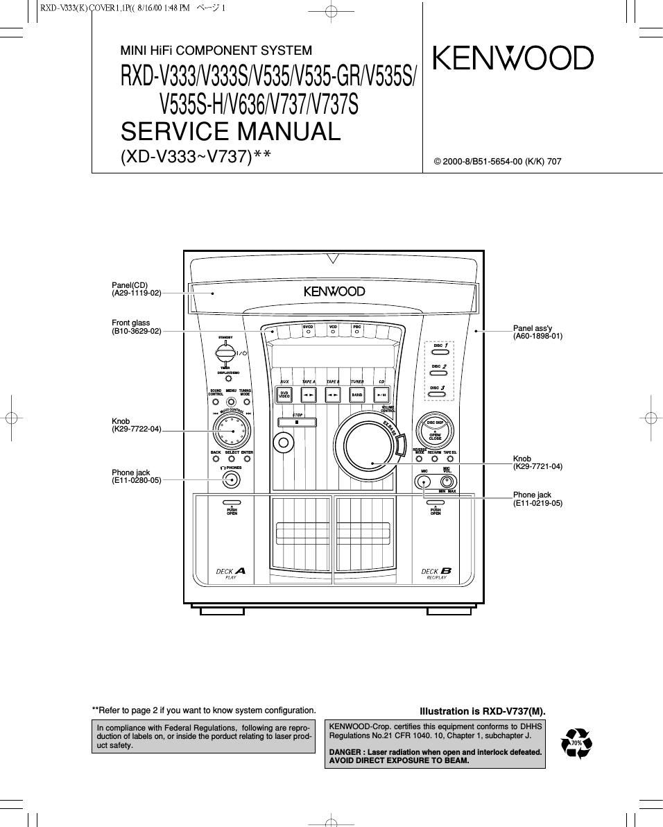
Kenwood RXDV 333 Service Manual

This is the 43 pages manual for Kenwood RXDV 333 Service Manual.
Read or download the pdf for free. If you want to contribute, please mail your pdfs to info@audioservicemanuals.com.

Page: 1 / 43
left right
Kenwood RXDV 333 Service Manual

Extracted text from Kenwood RXDV 333 Service Manual (Ocr-read)


Page 2

RXDEV333(K)COVER1,1P(( 8/16/00 1:48 PM «Ks/2 /\

FIXD-V333/V535//V636/V737

CONTENTS / ACCESSORIES

Contents

CONTENTS / ACCESSORIES ..
EXTERNAL VIEW ......................
DISASSEMBLY FOR REPAIR...

PC BOARD ......................
SCHEMATIC DIAGRAM ..
EXPLODED VIEW

aloh'm'ooix)

CIRCUIT DESCRIPTION. PARTS LIST ..............

ADJUSTMENT ................. .. PARTS DESCRIPTIONS ..54
WIRING DIAGRAM ................................................... 1 SPECIFICATIONS .................................................... 55
Accessories

FM indoor antenna (1)
(T90-0836-05)

AM loop antenna (1)
(T90-0852-05)

Remote control unit (1)
(A70-1415-05): RC-V535

unno'ooooooona
a momentum
on I onooooun

oooooouo

oooo o

Batteries (Re/AA) (2)

Battery cover (A09-1192-08)

AC plug adaptor (1)

Speaker cords
(E03-0115-05)

Video Cord (1)
(E30-1427-05)

M type only

XD-V636 (2)
XD-V737, XD-V737S (4)
Provided in the speaker package

Use to adapt the plug on the power cord to the Shape
of the wall outlet.
(Accessory only for regions where use is necessary.)

r\
\/

System configuration

SYSTEM MAIN UNIT DESTINATION SPEAKER SP CORD PARTS No
XD-V333 RXD-V333 MI LS-N373 E30-5829-08
XD-V333S RXD-V333S M2 LS-N373 E30-5829-08
XD-V535 RXD-V535 MIV LS-N573 E30-5829-08
XD-V535-GR RXD-V535-GR M1 LS-N573-GR E30-5829-08
XD-V53SS RXD-V5358 M2 LS-N573 E30-5829-08
XD-V53SS-H RXD-VSBSS-H M2 LS-N573-H E30-5829-08
XD-V636 RXD-V636 MI LS-N853 E30-5475-08
XD-V737 RXD-V737 MIV LS-N773 E30-5876-08
XD-V737S RXD-V737S M2 LS-N773 E30-5876-08
Cautions

Operation to reset

The microcomputer may fall into malfunction (impossibility
to operate, erroneous display, etc.) when the power cord is
unplugged while power is ON or due to an external factor.
In this case, execute the following procedure to reset the
microcomputer and return it to normal condition.

Unplug the power cord from the power outlet then,
while holding the ENTER key depressed, plug the
power cord again.

(Main unit only)

0 Please note that resetting the microcomputer clears the
contents stored in memory and returns it to the condition
when it left the factory.

I I J?

Page 5

RXDN333COVERL1P<< 8/16/00 1:48 PM «by s +
RXD-V333/V535//V636/V737

CIRCUIT DESCRIPTION

3-2 Cancel of the test mode

By turning the power off, the system is initialized and the test mode is canceled.
3-3 Contents of the Test Mode
3-3-1 Deck Test Mode

KEY DISPLAY OPERATION
It the REC/ARM key is pressed, the system record for 4 seconds. Then, it rewinds to the REC
starting position and plays back automatically. If the REC/ARM key is pressed, during the 4
REC/ARM Normal display seconds REC operation,the system records further for 4 seconds, then returns to the starting
position of the first 4 seconds REC operation and plays back.

*Mechanism SW Detection

HALF SW DISPLAY HALF SW DISPLAY
A PACK SW "T" (The first dot) A Cr02 SW "A"(The second dot)
B PACK SW P"(The third dot) B RVS REC SW "E"(The fourth dot)
B FWD SW "T"(The sixth dot) B Cr02 SW "E"(The seventh dot)
A PLAY SW "Moon"(Segment) B PLAY SW "Sun"(Segment)
3-3-2 CD Test Mode
KEY DISPLAY OPERATION
CD-PLAY/PAUSE 05 >l< >l< : >l< >l<
(>i< >i< : >i< >i< ) Tracking-servo on.
(Change the mode 05 and 03 03 ,7. ,, Tracking-servo off.
alternately by the stop key.)
(3 01301 01 77:77 STOP
Adjustment value/mean value
(Cyclically changed in the 07 >l< >l< / >l< >l< TB value FB value
stop mode only.) 08 >l< >l< / >i< >i< TG value FG value
09 >i< >i< / >i< >i< FE value RF value
10 >i< >i< / >l< >i< TE value VC value
STOP 01 ,7. ,7 Stop (Press it 1time.)
Cancel the test mode. (Press it 2 times.)
TAPE EQ. Ex.01~02 CD track no. up.
REVERSE MODE Ex.02~01 CD track no. down.