Kenwood RXDNV 301 Service Manual

This is the 41 pages manual for Kenwood RXDNV 301 Service Manual.
Read or download the pdf for free. If you want to contribute, please mail your pdfs to info@audioservicemanuals.com.

Page: 1 / 41
left right
Kenwood RXDNV 301 Service Manual

Extracted text from Kenwood RXDNV 301 Service Manual (Ocr-read)


Page 1

RXDeNV301(K COVER1,1P( 8/21/005:12 PM «HAS/1 /\
\/

EllE-TlePESl'lllleBTlEE/Nwo1/NV701E KENWOOD

SERVICE MANUAL
(NV-301/301 E/701/701 E)

© 2000-8/851-5657-00 (K/K) 3673

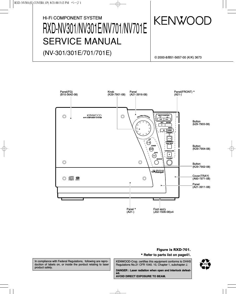
Panel(FG) Knob Panel Panel(FRONT) *
(B10-3642-08) (K29-7901-08) (A21-3916-08) (A21-)
0 KENWOOD
/ m-FILOMPONENTSVSYEM
Button
(k29-7903-08)
Button
(3 (K29-7904-08)
© Button
(K29-7902-08)
35:32:,
W ._ -Cover(TRAY)
© mg § © (A60-1971-08)
, Panel
(A21 -391 1-03)
E I- -l
Panel * Foot ass'y
(A21 -) (J02-1506-08)X4
Figure is RXD-701.
* Refer to parts list on page41.
In compliance with Federal Regulations, following are repro- KENWOOD-Crop. certifies this equipment conforms to DHHS .
duction of labels on, or inside the porduct relating to laser Regulations No.21 CFR 1040. 10, Chapter 1, subchapter J. 7004
product safety. I

DANGER : Laser radiation when open and interlock defeat-
ed.
AVOID DIRECT EXPOSURE TO BEAM.

l l 4

Page 2

RXDENV301(K)COVER1,1P( 8/21/00 5:12 PM ART) 2

r\
\/

RXD-NV301/NV301E/NV701/NV701E

CONTENTS / ACCESSORIES / CAUTIONS

Contents

CONTENTS / ACCESSORIES / CAUTIONS
EXTERNAL VIEW ......................
DISASSEMBLY FOR REPAIR...
CIRCUIT DESCRIPTION.
ADJUSTMENT ...........
WIRING DIAGRMA....


PC BOARD ........................
SCHEMATIC DIAGRAM.
EXPLODED VIEW .............
PARTS LIST ....................
SPECIFICATIONS ..........

Accessories
f \
FM indoor antenna(1) AM loop antenna (1) Remote control unit(1)
T -0 -0 T 0-0 04-08
I 90 830 BI I 9 8 I (A70-1459-08): ETE2 (A70-1460-08): ETE2
(A70-1475-08): KMX (A70-1461- 8): KMXY

Speaker cords
NV-3D1 (2)
NV 701 (6)

Batteries (FIG/AA)

(Speaker cords are provided

in the speaker package. Be
sure to check that the correct

lengths have been provided.)

System configurations(RXD-NV301/NV701)

Dooooofl nuq (illoooo unnnq \
unnonD unnn (nunun DDIJD
unuuu unnnl) uuuuu uuunl)
Iconoo no lnuonn DIZIIJIJo
RC-NV301E RC-NV701E
FIC-NV301 FIC-NV701

AC plug adaptor (1)
(E03-0115-05)

w Use to adapt the plug on the power cord
In to the shape of the wall outlet.
(Accessory only for regions where use is

necessary.)


SYSTEM MAINUNIT DESTINATION SPEAKER SPCORDPARTSNo SPEAKER SPCORDPARTSNo
NV-301 RXD-NV301 KMXTE LS-NV701 Eso-ssoo-os - -
NV-301E RXD-NV301E E2 LS-NV701 Eso-ssoo-os - -

an-ssss-os
NV-701 RXD-NV701 KMXYTE LS-NV701 E30-5500-05 CRW-NV701 E30_5859_05

Eso-sess-os
NV-701E RXD-NV701E E2 LS-NV701 E30-5500-05 CRW-NV701 E30_5859_05
Cautions

Operation to reset

The microcomputer may fall into malfunction (impossibility
to operate. erroneous display, etc.) if the power cord is
unplugged while power is ON or due to an external factor.
In this case, execute the following procedure to reset the
microcomputer and return it to normal condition.

Unplug the power cord from the power outlet then, while
holding the SET (0) key depressed, plug the power cord

again SET

SQ

(Main unit only)

0 Please note that resetting the microcomputer clears the
stored contents and returns to the factory set condition.

8);

Page 20

RXDiNV301(K)PCBSDZ,2P( 8/21/00 5:13 PM \°~/~ 7

SURROUND BOARD MAlN
-| .cpm
1 mm egg m 51 §§l§ . l we
. a- om am am Com mam
rm . . Al 3% 2% g .sv 10.4145 we w my on; | ©
é: a = .. a i :1 W rm
W W 52 can RM am am 6 7
GND 2 a s c s 2 a a a $ 4x :1 . 5 mm W WK was Tl\ 5 < FLOW
, E: as a 5 . . .
> g g 23 24v ' ° :g RMSL A a n W2)
=2 m 2. gm e $13339
mm mm hi g , lemma/2) , §.
Rm 3 M 7" iii
. .lzv
em ANALOG mwms 25 V
3° "1" momvrsneé 28 V
on Rmmcz
g s V s e s
.5v . W § .sv .sv ,1 .5v my a
m l d5 g g g; gal
2 GND 5 i 27 10K ; i E 5 H °
NV 32 2 a a a DD flfl _ 2 GND
; E a : w w : mam
8 23 24v m a s o .7 c
A E h ow
3 $55 29 a ms 1 mm
5 on > m .
o 3;; a 2 man mm awn cmR own REESE n g :
° g . mulls ma 31x map muss 22K if V g
i . K .7
an i g Eé ICsaB K
cEN Mm: @4432 > «s /21 g 5 am:
WW 0% m MicRoPRocEssEoR cosmclzw K 1 a y . a
mama pmwm g m 2 , a
suRRMmE 0A3; «2 K, x: K x ; w
mszLv ofiu 0 uv :3 3% Hum g E:
szRRLv .fias or
'0 n a coNrRoleeNALs coNvRoLsiemLs g ¥ K
Rm Icsoz 3 ~ 3 .
1K {BOWOM VIEW) CONVROLREGlSYERS V55 5 41V
cow 1 g n; n w. cENrER 417v
2" cm 22mm to W K CEMC mus mo cm 11 5V
> 1. m m l was m W W .m
g cozzlmaP . o
3 . s a: e e W a
> g a EN 1% a Na l g.» 5 cmzc mm
M n 7 , 5% > 3x ,L mm m
TI s E 83 §N a 5 com
sous u 69 5w SDlECK sEL SDOECK SEL K, o 91
SBA/so i 67 V L33: R5212: év T L 5% We '32? at E 1
mg. 14 as 5 r g 1 15K 3% v a "$5
cs 15 4456 m. t. K t. g a , .
m 455 l-zm-mv my 3 a A g A a u 15v a em)
a E a E :5 22 g m W 11
> 7 z .m , E cuesw wantsw auzsw MSW
ADO/CS a w i s g 7 w; m 5 V «of mm ma 15x lamp
m a g g g o . > > > >
T " 7 '" 3 i .0505 ? ¥ ? 5.
0P" 5w fl is 5:5 m) mm
V0!) 5 g g I 1 mm
. av .5v "1 "k ' 7 SUE OW
m. s m . .
Gm, , cm Ham l 6, :2 gr saw
no: no 3; 0 :A o m5sw 3
your as g
g > a s 1 12K §
§, 3 3§ 3 s: > > 3 3 "' a §
0mm | 07:7 8 8 r w 7 §~
s a mm
m <. <¥
4 acml 0:35 W W is ,V 12V
commit an zs RSElSL amt camel w
gnffl' § w m a; 5 we ask lump olzv
fi 5 L
o I a R852 mK 8 go roam
" 2/2
am. a E m Rammk Kw 15f CWSL mm
2 § a g 4 § SW go a a 7 55 K 9 SLOW
§ § ">2 3 r a K §5 é* a Him a .
a K 8 8 3 nasmk 7 .% A fig 2 x
§§ R857 ovamme CLOCK év 5 we 8 E
OPI' LACKT - Rosa IDK n E K m END
w 7 case-sh laws»: Raazsa omen
: I .5v SV mm m m map > > > >
Icsoa :mumw . a g a g g
Icsosreus | x h 31 ,,,,, 3% room . .
:vasasmn I £3 g; .73 a (ml at? Ragga
K' m K 1 u
usm orcmvs ; g gé gm , .. mm
usuasm - no 11
5 rcmrs I > K 8 as b mssn 1 {5 x
06172504505 | w a g: 1 tax fi 5
orAmvs :' .azv mm s 8, g
decasos | 5 a a mm.
ZSKIINYl g > I GND
I r so
: szIaasn I on van m on
D605 82 1-
I ; §§
DlGlTALlJNE I , _,, ,V W
SIGNALUNE mm
- sun UNE I .9 45v 42v rtZV<--*@-11V
flak; E LlNE .301 may Rfiam 42V .12V b-I sz
fies 43 WE | 7 -
L__________________________________________________________________________________________
HXD-NV701 (E

CAUTION: For continued safely, replace safety critical components only with manufacturer's
recommended parts (refer to parts list). A indicates safety critical components. For continued
protection against risk of fire, replace only with same type and rating fuse(s). To reduce the
risk of electric shock, leakage-current or resistance measurements shall be carried out
(exposed parts are acceptably insulated from the supply circuit) before the appliance is
returned to the customer.

The DC voltage is an actual reading measured with a
high impedance type voltmeter with a cassette loaded
at playback mode. The measurement value may vary
depending on the measuring instruments used or on
the product. Bias circuit DC voltage is measured while
in the record mode.

DOLBY and the double-D symbol are trade-
marks of Dolby Laboratories Licensing Cor-
poration. Noise reduction circuit made under
license from Dolby Laboratories Licensing
Corporation.

Y39-3640»10

RXD-NV701/NV701 E