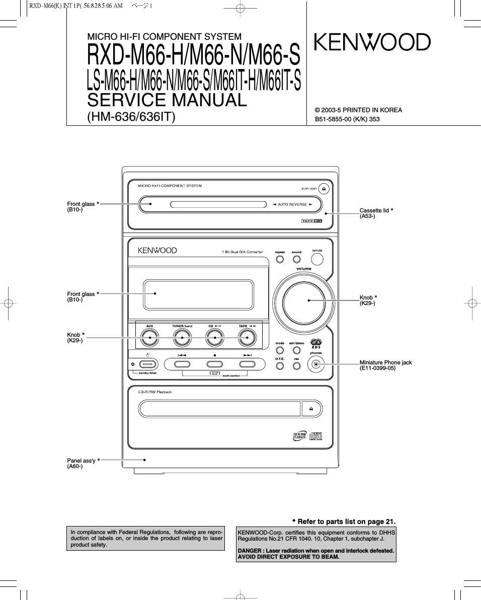
Kenwood RXDM 66 Service Manual

This is the 23 pages manual for Kenwood RXDM 66 Service Manual.
Read or download the pdf for free. If you want to contribute, please mail your pdfs to info@audioservicemanuals.com.

Page: 1 / 23
left right
Kenwood RXDM 66 Service Manual

Extracted text from Kenwood RXDM 66 Service Manual (Ocr-read)


Page 1

RXDrMGG(K) INT 1P( 56.8.28 5:06 AM «3? 1 K \

MICRO HI-FI COMPONENT SYSTEM

RXD-M66-H/M66-N/M66-S KENWOOD
LS-M66-H/M66-N/M66-S/M66i-HlM66i-S

SERVICE MANUAL
(HM-636/636IT)

© 2003-5 PRINTED IN KOREA
B51-5855-00 (K/K) 353

MICRO Hl-Fl COMPONENT SYSTEM a .n F
From glass * :3 < » D
(310') K Cassette lid *
w (A53-)
IEE
KENWOOD t Bu Dual D/A Conveuer "pm mum m
N O Q 0
volume
Front glass * -' *
r 810- Knob
Q I I (K29-)
Alix YuNER/band
Knob * flih fl
9-) ivw v
L) |«
@ (_) Miniature Phone jack
C (E11-0399-05)
memw [W31
mm: n...
CDrH/RW Playback
C Q)
CIHt/RW m
Luv/I @flglfi
Panel ass'y * -°
(A60-) I

° Refer to parts list on page 21.

product safety

In compliance with Federal Regulations, following are repro-
duction of labels on, or inside the product relating to laser

KENWOOD-Corp. certifies this equipment conforms to DHHS
Regulations N021 CFR 1040. 10, Chapter 1, subchapter Jt

DANGER : Laser radiation when open and interlock defeated.
AVOID DIRECT EXPOSURE TO BEAM.

#

Page 2

RXDsMGG(K) INT 1P( 56.8.28 5:06 AM N? 2 K \

RXD-M66/LS-M66

ACCESSORIES / CAUTIONS

Attention
Please contact our KENWOOD Service Department in your side if you want the sen/ice information; Circuit Description. Full
Described Parts list and so. Information is available to you by internet from us. On circuit description, refer to RXD-M55.

Accessories

Remote control unit (1)
(A70-1568-05): EE1 E2
(A70-1569-05): M1 X1X2

AM loop antenna (1)

(T90-0893-05) AC Plug Adaptor (1)

(E03-0115-05)
Use to adapt the plug on the

9 power cord to the shape of the
'1 wall outlet.
(Accessory only for regions where
use is necessary.)

Batteries (HG/AA) (2)

as

FM indoor antenna (1)
(T90-0877-05)

System Configurations

SYSTEM RECEIVER SPEAKER
HM-636-H FtXD-M66-H LS-M66-H
HM-636-N FtXD-MGG-N LS-M66-N
HM-636-S RXD-Mee-s LS-M66-S
HM-636lT-H FtXD-MGG-H LS-M66lT-H
C3 HM-636IT-S RXD-M66-S LS-MGGlT-S
Cautions

Operation to reset Note related to transportation and movement

The microcomputer may fall into malfunction (impossibil-
ity to operate, erroneous display, etc.) when the power
cord is unplugged while unit is ON or due to an external
factor. In this case, execute the following procedure to
reset the microcomputer and return it to normal condi-
tion.

0 Please note that resetting the microcomputer clears
the contents stored in and it returns to condition
when it left the factory.

Unplug the power cord from the power outlet, then

while holding the POWER or (5 key depressed, plug
the power cord again.

After resetting the microcomputer, the display will show
as follow:

Before transporting or moving this unit, carry out the follow-
ing operations.

0 Remove the CD from the unit.
9 Press the CD NII key.

0 Wait for some time and verify that the display
appears as above.
0 Wait a few seconds and turn the unit OFF.

CLASS 1
LASER PRODUCT

The marking of this product has been classiiied as Class 1. It means
that there is no danger of hazardous radiation outside the product.
Location Back panel

The marking of products using lasers (For countries other than U.S.A., U.S.-Military and Canada)

CAUTION
VlSlBlE LASER RADlATlDN
WHEN OPEN Do Nor suns
mm mm on will! mainly
wmt oPtIcAL leTRvMENrs

inside this laser product, a laser diode classified as Class 3A laser
radiation is contained as alerted by the internal caution label shown
above. Do not stare into beam or View directly With optical instruments

dii

Page 5

RXDEMGG(K) INT 1P( 56.8.28 5:06 AM «>3; 5 +
RXD-MBB/LS-MBB

ADJUSTMENT

CD player adjustment

INPUT OUTPUT PLAYER ALIGNMENT
N°' EM SETTING SETTING SETTING POINT AUG" FOR F'G'
Insert the AC cord to AC wall outlet while holding down the [CD PLAY/PAUSE] key.
Connect the DC .. ..
- Press the PLAY key
LASER TGSt dISC voltmeter to .

1 . to check that the dIs- - 220mV to 550mV

CURRENT Type 4 CN23(#;(§Igd #2) In play is 03.. or "05..

Note:

Type 4disc :SONY YEDS-18 Test Disc or equivalent. (KTD-02)
LPF : Around 47kQ + 390pF or so.

Cassette Deck adjustment

0st=0.775V
INPUT OUTPUT DECK ALIGNMENT
N° 'TEM SETTING SETTING SETrING POINT AL'GN FOR F";-
I . CASSETTE MECHANISM UNIT
Demagneti- . Demagnetize the REC / PLAY head
Demagneti» zation: hgegordlnge with the head eraser. Clean the REC
< 1 > zation and - - POWER OFF he; caersatim / PLAY head, erase head,capstan and
cleaning Cleanlng: inch rgller pinch roller using a cotton swab
PLAY p slightly damped with alcohol.
- SOC-1727 Adjust the output to maximum and
AZ'Thuéh Of T007153 adjust the azimuth adjustment screw
< 2 > REC/PLAY MTI'71 14 (A) PLAY (x Q for the Lissajours waveform pattern of
head 10kHz, " J the oscilloscope to become close to a
7 10dB RVS FWD 45" straight line.
T007110
. . heck the ta e s eed so that
m TAPE SPEED MTH 11 TrImmIn pot C ., . P . p
x 2 < 3 > (NORMAL) 80071727 (A) PLAY in the mgtor. 3kHz(¢2 /o) Isfcilfitalned at the center
3kHz o e tape.
11. PC BOARD ADJUSTMENT
C (mt th
Agrtgjacke VR 1 (L) Record 1kHz and 10kHz alternately,
1 BIAS 1kHZ' ' (A) REC and VR 2 (R) and adjust the bias current adjust- Fig.1
< > CURRENT -30st PLAY (X28) ment potentiometer for the playback
10kHz: levels (-21st)to become the same.
-30st
SYSTEM CONNECTIONS
X28 CN1

(TAPE Lch),3 pin

a (TAPE Rch),5 pin

Oscilloscope AC voltmeter

Frequency counter