Kenwood RXDM 51 MD Service Manual

This is the 46 pages manual for Kenwood RXDM 51 MD Service Manual.
Read or download the pdf for free. If you want to contribute, please mail your pdfs to info@audioservicemanuals.com.

Page: 1 / 46
left right
Kenwood RXDM 51 MD Service Manual

Extracted text from Kenwood RXDM 51 MD Service Manual (Ocr-read)


Page 1

RxorMblMDIK) COVER1,lP( 98.12.1019:11 y [ w 2

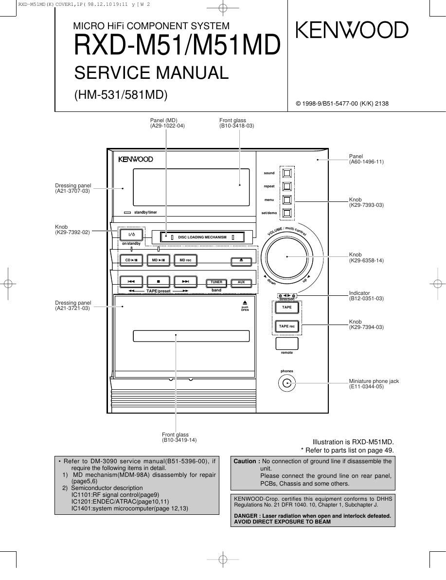
MICRO HiFi COMPONENT SYSTEM

RXD-M51/M51MD KENWOOD

SERVICE MANUAL
(HM-531/581 MD)

Dressing panel
(A21 -3707-03)

Knob

(K29-7392-02)

Dressing panel

Panel (MD)
(A29-1022-O4)

/\
K

© 1998-9/851-5477-00 (K/K) 2138

Front glass
(810-3418-03)

KENWOOD

Panel
%(A60-1496-11)

IEI
W. IEI
1&1

Knob

I:I standby/timer

(K29-7393-03)

set/damn '

l/d)

It,

-| q
|] DISC LOADING MECHANISM l]

093 l mun,- a,
»

I on/slandby I

(A21-3721-03)

I Indicator
(812-0351-03)

II
1 I .-7Knob
I cn>III MD >III I MDrec f-] T] 3 (K29-6358-14)
3 a; I
l I I I I I W I TUNER | Aux
I I I I I I II II II II
I 44* TAPE/preset 4» band

Knob
(K29-7394-03)

TAPE m:

remole

phones

. Mmiature phone lack
(E11-0344-05)

From glass
(B1 0-3419-14)

Illustration is RXD-M51 MD.
* Refer to parts list on page 49.

~ Refer to DM-3090 service manuaI(B51-5396-OO), if

require the following items in detail.

1) MD mechanism(MDM-98A) disassembly for repair

(P519355)

2) Semiconductor description
IC1101zRF signal control(page9)
|C1201:ENDEC/ATRAC(page10,11)
IC1401:system microcomputer(page 12,13)

Caution : No connection of ground line it disassemble the
unit.
Please connect the ground line on rear panel,
PCBs, Chassis and some others.

KENWOOD-Crop. certifies this equipment conforms to DHHS
Regulations No.21 DFR 1040. 10, Chapter 1, Subchapter J.

DANG ER : Laser radiation when open and interlock defeated.

AVOID DIRECT EXPOSURE TO BEAM

L

Page 2

JRXDaMSlMDlK)CO\/ER1,1P( 98.12.1019111 y [w 3 44%
RXD-M51/M51 MD

CONTENTS / ACCESSORIES / CAUTION


Contents

CONTENTS / ACCESSORIES / CAUTION ................. 2 PC BOARD .......................
EXTERNAL VlEW/DISASSEMBLY FOR REPAIR ....... 3 SCHEMATIC DIAGRAM
BLOCK DIAGRAM ............. ...4 EXPLODED VIEW
CIRCUIT DESCRIPTION ...5 PARTS LIST ..........
ADJUSTMENT ................... 11 SPECIFICATIONS
WIRING DIAGRAM .................................................... 12

Accessories
r

N
Please confirm that the following accessories are present.
- - FM indoor antenna (1) - , l- Loop antenna (1) (T90-0833-05) -
1 Europe UK and Russia Other countries I I AM loop antenna stand (1) 1
I (T90-0810-05): TE (T90-0801-05): M : I (.119-3645-05» I
I I : I
I : a I
I ' . I
1 i : ' 1
AC plug adapter (1)
(E03-O115-05) _
i , Speaker cords (2) BatterIes (RS/AA) (2)
(E30-5500-05)
Use to adapt the plug on the power 77 ' r '
\ cord to the shape of the wall outlet.
c (Accessory only for regions where
use IS necessary.
Remote control unit (1) Remote control unit (1) Remote control unit (1)
(A70-1236-05) : RC-M0503E (A70-1242-05) :RC-F0503E (A70-124I-05) : Rc-F0503
J
System configuration
SYSTEM MAIN UNIT DESTINATION SPEAKER SP CORD PARTS.NO.
HM-581MD RXD-M51MD E1T1 LS-M61 E30-5500-05
HM-531 RXD-M51 M1 E2T2 LS-M51 E30-5500-05
Caution
Operation to reset
The mIcrocomputer may fall Into malfunctlon (Imposs'bll' Unplug the power cord from the power outlet then, while
Ity to operate, erroneous display, etc.) when the power . .. ,,
. . . . hoIdIng the set/demo key depressed, plug the power
cord Is unplugged thIe unIt Is ON or due to an external cord a ain
factor. In this case, execute the following procedure to g '
reset the microcomputer and return it to normal condi-
tion. I: d
0 Please note that resetting the microcomputer clears the 53 emu K5
contents stored in and it returns to condition when it left
the factory.