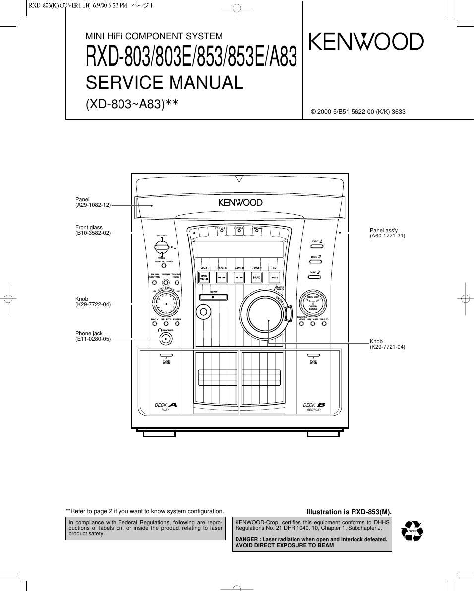
Kenwood RXD 853 Service Manual

This is the 35 pages manual for Kenwood RXD 853 Service Manual.
Read or download the pdf for free. If you want to contribute, please mail your pdfs to info@audioservicemanuals.com.

Page: 1 / 35
left right
Kenwood RXD 853 Service Manual

Extracted text from Kenwood RXD 853 Service Manual (Ocr-read)


Page 1

RXD7803(K) COVER1,1P( 6/9/00 6:23 PM \°-/1 /\
\/

El31§3§l§5§E7§T§§/853E/A83 KENWOOD

SERVICE MANUAL
(XD-803~A83)**

© 2000-5/851-5622-00 (K/K) 3633

-
Panel
(A29-1 082-12) -. KENWOOD
From glass Panel ass
Y
(810-3582-02) (A60-1771-31)
r \
Knob
\ / (K29-7722-04)
Phone jack 0mm
(EH-028005) l © $120; 7721 04)
g
l
DECKA ,\\* *!'* , DECK B
PLAY \*7777 7 7 77777777- REC/PLAY
I-l I-l
"Refer to page 2 it you want to know system configuration. Illustration is RXD-853(M).

in compliance with Federal Regulations, following are repro- KENWOOD-Crop. certifies this equipment conforms to DHHS .
ductions of labels on, or inside the product relating to laser Regulations No 21 DFR 1040. 10, Chapter 1, Subchapter J. 701/.
product safetyt a

DANGER : Laser radiation when open and interlock deleated. -~
AVOID DIRECT EXPOSURE TO BEAM

l l 4

Page 2

r\
\/

RXDE803(K) COVER1,1P( 6/9/00 6:23 PM \°-/ 2 K \

RXD-803/803E/853/853E/A83

CONTENTS / ACCESSORIES

Contents

CONTENTS / ACCESSORIES / CAUTIONS
EXTERNAL VIEW .........................................
DISASSEMBLY FOR REPAIR...
BLOCK DIAGRAM ...........
CIRCUIT DESCRIPTION. ..
ADJUSTMENT .......................................................... 1

ain'b'm'mm

PC BOARD ......................
SCHEMATIC DIAGRAM ..
EXPLODED VIEW
PARTS LIST ........
SPECIFICATIONS

Accessories
,

FM indoor antenna (1)
(T90-0836-05)

AM loop antenna (1)
(T90-0852-05)
(T90-0837-05)

Remote control unit (1)
(A70-1367-05): RC-853....KPMXY
(A70-1368-05): RC-853E....TEE2

Batteries (Re/AA) (2)

Battery cover A09-1151-08)

AC plug adaptor (1)
(EO3-0115-05)
V Use to adapt the plug on the power
"r cord to the shape of the wall outlet.
(Accessory only for regions where
use is necessary.)

Surround speaker system

Surround speaker (2)
Speaker cord (2)
Speaker stabilizer (8)

Center speaker (1)
Speaker cord (1)
Speaker stabilizer (4)

SYSTEM CONFIGURATION

SYSTEM MAIN UNIT DESTINATION SPEAKER SP CORD PARTS No. SPEAKER SP CORD PARTS No.
XD-803 RXD»803 E LS-N523 E30»5829-08 CRS-N503 E40-5542-05
XD-803E RXD»803E E2 LS-N523 E30-5829-O8 CRS-N503 E40-5542-05
XD-853 RXD-853 YMXTE LS-N573 E30»5829-08 CRS-N553 E40-5542-05
XD-853E RXD-853E E2 LS-N573 E30-5829-O8 CRS-N553 E40-5542-05
XD-853(M3) RXD»853 M LS-N573(M3) E30-5829-08 CRS-N553 E40-5542-O5
XD-A83 RXD-A83 KP LS-N573 E30-5829-08 CRS-N553 E40-5542-05
Cautions

Operation to reset

The microcomputer may fall into malfunction (impossibility
to operate, erroneous display, etc.) when the power cord is
unplugged while power is ON or due to an external factor.
In this case, execute the following procedure to reset the
microcomputer and return it to normal condition.

Unplug the power cord from the power outlet then,
while holding the ENTER key depressed, plug the

power cord again.
ENTER

0 Please note that resetting the microcomputer clears the
stored contents and returns to the factory set condition.

(Main unit only)

8);

Page 9

r\
\/

RXD7803(K) COVER1,1P( 6/9/00 6:23 PM \°-/ 39

/\
\/

RXD-803/803E/853/853E/A83

CIRCUIT DESCRIPTION

Pin No. Pin Name l/O Description H mm L
41 EX CLK15 O Clock output to expander |C(X13,IC15).
42 PS LOAD 0 Control port of shift/load tor expander |C(X13,|015). SHIFT LOAD
43 PS IN 0 Data input from expander |C(X13,|015).
44 EX CLK16 O Clock output to expander |C(X13.IC16).
45 EX DATA 0 Data output to expander |C(X13,|016).
46 ATT O >10dB attenunation output. OFF ON
47 FL RST 0 Reset signal output to VFD dot driver. RESET
48 LED PRO 0 LED output for prologic. OFF ON
49 LED SST 0 LED output for 3 stereo. OFF ON
50 LED VIR 0 LED output for virtual. OFF ON
51 M CONT B | Multi control jog input .
52 M CONT A | Multi control jog input .
53 VOL B | Volume encoder input .
54 VOL A | Volume encoder input .
55 LED STBY 0 Control port of standby LED. OFF ON
56 LED TIMER 0 Control port of timer LED. OFF ON
57 NC - Unused.
58 OPEN SW | CD open detection switch input.
59 CLOSE SW | CD close detection switch input.
60 TD SW | Traverse down switch input port of CD mechanism.
61 TU SW | Traverse up switch input port of CD mechanism.
62 VCC(BU) - u-com power supply(+5.0V).
63 OPEN 0 CD motor control output.
64 V88 - GND.
65 CLOSE 0 CD motor control output.
66 BRKM 0 CD motor control output.
67 RTL 0 Rotary motor opposite direction(CCW) output.
68 RTR 0 Rotary motor positive direction(CW) output.
69 DC OFF 0 Power control of CD DSP IC. ON OFF
70 CD PROT | CD protection input(Only at selector CD). NORMAL PRO. ON
71 SLT SW | CD start limit switch input.
72 MLD 0 CD DSP command load signal output.
73 SQCK 0 CD sub code clock output.
74 SUBQ | CD sub code input.
75 D MUTE 0 CD DSP muting output.
76 XRST 0 CD DSP IC reset control. RESET
77 PHTR | CD mecha. Stop switch input.
Tray position & disc detector switch input port of

78 PS SW I CD mechanism.
79 TU ON/OFF 0 Tuner power on/ott output.
80 REC/PLAY O Deck recording/playback control. RECORDING PLAYBACK
81 BIAS O Deck bias control. OFF ON
82 POWER 0 Power relay control.
83 RELAY 0 Control port of speaker relay.
84 EV CLK O Clock output to E..volume.
85 EV DATA 0 Data output to E..volume data output.
86 EMPHASIS 0 Tuner emphasis output.
87 EPROM DATA I/O Expander ROM data input/output.
88 EPROM CLK O Expander ROM clock output.
89 PROTECT | Detection port of protection.
90 SPEANA | Input port of music signal.
91 TYPE I Discrimination of tuner destination.
92 BPH | B deck reel sensor input.
93 APH | A deck reel sensor input.

94,95 KEY3,KEY2 | ND key input(key3,key2).
96 AVSS - GND.
97 KEY1 | ND key input(key1).
98 VREF - A/D reference voltage input.
99 AVCC(BU) - u-com power supply(+5.0V).
100 PLL DATA PLL IC & E..volume data output.

ztxi