Kenwood RXD 701 W Service Manual

This is the 57 pages manual for Kenwood RXD 701 W Service Manual.
Read or download the pdf for free. If you want to contribute, please mail your pdfs to info@audioservicemanuals.com.

Page: 1 / 57
left right
Kenwood RXD 701 W Service Manual

Extracted text from Kenwood RXD 701 W Service Manual (Ocr-read)


Page 1

RXDE501~751(K)COVER(98t4t23le42 y [w 2 if

MINI HiFi COMPONENT SYSTEM

RXD-501/501E/501W/551/551E/551W/5718/A5/ KENWOOD
701/701 E/701W/751/751E/751W/7718/A8

SERVICE MANUAL
(XD-501~A8)**

© 1998-3/351-5420-00 (K/K) 3661

L

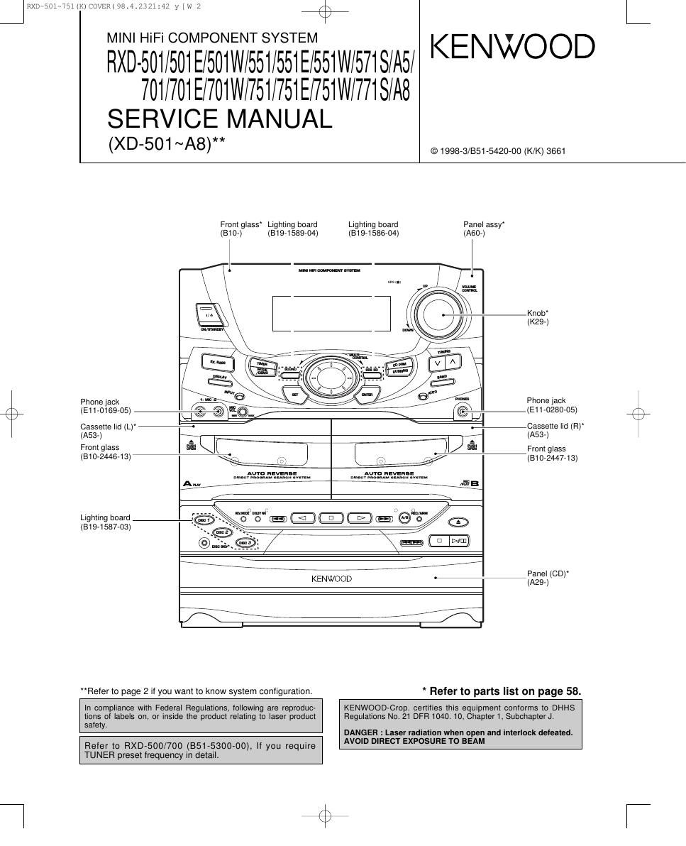
From glass Lighting board
(810-) (B19-1589-04)

Lighting board
(B19-1586-04) (A60-)

MINI in cnmzm 5mm

Phone jack 1 I
O (E11-0169-05) lK-l w @ (EON
Cassette lid (L)

5.5 (m

(A53-)

Front glass
(310-2445-13)

AUTO REVERSE

Amy

AUTO REVERSE

Lighting board
(B19-1587-03)


a

KENWOOD

"Refer to page 2 if you want to know system configuration.

Panel assy

Knob
(K29-)

Phone jack
(E11-0280-05)

Cassette lid (RV
(A53-)

From glass
(310-2447-13)

Panel (CD)
(A29-)

* Refer to parts list on page 58.

In compliance with Federal Regulations, following are reproduc-
tions of labels on, or inside the product relating to laser product
safety.

Refer to RXD-500/700 (851-5300-00), If you require

KENWOOD-Cropt certifies this equipment conforms to DHHS
Regulations No. 21 DFR 1040. 10, Chapter 1, Subchapter J.

DANGER : Laser radiation when open and interlock defeated.
AVOID DIRECT EXPOSURE TO BEAM

TUNER preset frequency in detail.

Page 4

JRXD7501~751(K)COVER(98.4.2321:43 y [w 7 44%
RXD-501/551/57i/A5/701/751/771/A8

DISASSEMBLY FOR REPAIR

1. How to remove the front panel.

(1) Turn the power ON and then push the open/close
key to open the tray.

(2) After removed the tray cover, push the open/close
key to close the tray and then turn the power
OFF.

(3) Remove the push rivet ((D) and 4 screws ((2), (3)).

(4) The front panel can be separated by removing the
3 screws (CD) located at the bottom plate of the
front panel.

2. How to remove the CD mechanism
(1) Remove 4 screws (6)) on the left side/right side of
chassis.
(2) Remove 2 screws ((6)) and the cap ((7)) on the
rear panel.
(3) Disengage the CD mechanism as FIG.2.

Fig.1

3. How to open the tray if not comes out.

k (1) From the rear side of the CD mechanism, use a
screw driver or the like to turn the friction arm fully
counterclockwise

(2) Pull out the tray front wards by hand when the
tray comes just out.

As for details of items in the below, refer to RXD-F3
service manual (851-5091-00).
(1) How to detach the tray.
(2) How to attach the tray.
(3) Replacing the pickup.

Page 23

I{XD*bOl~'/bl (K) SD ( 98.4.2322102 y [W 6


CAUTION: For continued salety, replace safety critical components only with manu-
facturer's recommended parts (refer to parts list). & indicates safety critical compo-
nents. For continued protection against risk Of fire, replace only with same type and

rating fuse(s). To reduce the risk 01 electric shock, leakage-current or resistance
measurements shall be carried out (exposed parts are acceptably insulated from
the supply circuit) before the appliance is returned to the customer.

The DC voltage is an actual reading measured with a high impedance type volt-
meter. The measurement value may vary depending on the measuring instruments

used or on the product. Refer to the voltage dur ing PLAY unless otherwise speci-

fied; The value shown in (

Y39-2850-10

+5V +5V +5V Ic1 c> 5 V I Ic2 cxozsam
is Ica : BA58785
EXCEPT 104 5 . TASAOBS
K,P TYPE
> I ) QI 25A854(L,K)
R2 ca R25 2 05,7 DT012AESA or uN4212
10)? 0.047 3.3K OB : 255764IE,F)
§ E 25v D15 Issm Ian-(5510M
> > > /-
I; :1 if) _,
m In In
.0 In .n
E :1 5 E n
d u 52
_________________________________ | 53
SlGNALI 491/ a: USED EXCEPT
-- DIGITAL DIGITAL DIGITAL I 54 cm (KP) TYPE (K,P) TYPE
PLL i CLV ouT -I I M, __ __ _ _ _
I + [-1 I- cza
I I I I V . 55F RXDVAS/Aa 06273590710)
XI Xt DESTINATION
' 15.8344MH2 I ' 188344MH2 I I COUNTRV AEB UNIT No 9,273}; R28 R8751 (52"
ERROR --- u, K
coRREcTOR DIA I 0710 NO 381: NO VES
INTEREAcE m E IT ' I I CANADA P
E v I E' I 5'
'H-b-II . . 43' |
EM L - J I ' ExcEPT RXDVAS/AS (X3273592771)
DEMoDuRAToR I IIng I XTAD 57 151/ *st 024 I UNIT ND Cfifi R28 R87; V542
'158 SEP
xvss
I l - - - I
| | ___l
I I I I 2771 VES ean VES NO
I I SERIALrlN TIMING
I I INTEREAcE LOGlC I AVDDI 59
I l | 4+B<- R71 R75 R77 I
I I IAOuTI 7o 2,1I/ 22 3.3K 2.7K
l l OVER SAMPLING 7947K I
SERVO I I DIGITALEILTER gll-t n3 IL X *w41 h l
AUTO | l 8 8 Nu m c:
SEQUENCER I I 49v 0 9 mm mm X I? §
I _, no 3 R85 043 El
I I E l I-I> 9&1 I8 R83 22 2.2.50 J. ,
I I u. I I I 22 '1' + Q LO X097A/7
SUBCODE u: AVSSI <1 0. .
- PROCESSOR ' ' 5% I I on R84 01's CN15
I ' art I 74 330u6.3 £2 ® AGND
~ I I III Avssz ogl Nx N51
/ \ I I 93$ 1- ILOUTZ 75 + D. 53 31; 50']: H2826 2.023450
K/ I I go i s g :e * *w42 I @ ROUT
O O o c:
I I "z I m r 3 *RBD m EL +5v @ st
I I § AIN2 7s m 3
CPU E R72 R75 0 N © DGND
lNTERFACE I I u. - IAOUTz 77 2.1V 22 33K 47K * N
_. I I I I R38 02 *(+9V(¥® Msv
| |
_______ ____ J I DAC BLOCK I I M 0.01 @ MGM?
- - - 73 B R46 5v T
+ +
(0 I
say?
a
* cm;
In x F E AMa)-_ RMR
E g j I; AM7)-® BRKM
X I AMEN-(3) RFS
m N : AM2)-® sTsw
E E .2 gggyw AMIl-GD ADSW
@ ZERO
"D On- so
gay 3% gx >3 1)7® soso
2 E. SQCK xoerA/7
In N 8 PG) stT .CNIQ
T T 5 )7® DATA
6 )7® > m 7 )7® CLOK
35 a 8 )-@ SENS >-®
03 + +
m 9 )-® SCLK
20)-® SCOR
+5v I 85v
@ LDoN
(I) MON
+sv +sv @ UGND
g D ; m |C4 ~<¢5V<~® U+5V
8 L2) (25 g 8 g AMIoH® LMR
n v In 191 E I: g AM11)-@ LMF
TRAY egg/Iv > TRAYCLg§- jMH-g TDSW
' m ' M3? WSW RXD-AS/A8(K) (1/8)
+
cez 'X
moi/(III $9 Amt-Q} LDSW RXD-501/501E/501W(E) (1/8)
1 \WV J- ' Amt-QB ULSW_ RXD-551/551E/551W/57IS(E) (1/8)
; $ T RXD~701/701E/701W(E) (1/8)
RXD-751/751E/751W/771S(E) (1/8)
+5v +5v I
J |

) is the voltage measured at the moment of STOP.

RXD-501/551/57l/A5/701/751/77l/A8