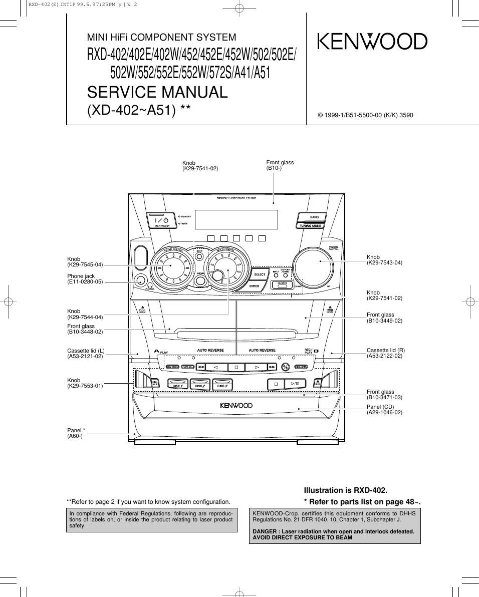
Kenwood RXD 402 Service Manual

This is the 47 pages manual for Kenwood RXD 402 Service Manual.
Read or download the pdf for free. If you want to contribute, please mail your pdfs to info@audioservicemanuals.com.

Page: 1 / 47
left right
Kenwood RXD 402 Service Manual

Extracted text from Kenwood RXD 402 Service Manual (Ocr-read)


Page 6

row-402(3)1NT1P99.6.97;25PM y [w 11

RXD-402/452/502/552/5728/A41/A51

we

CIRCUIT DESCRIPTION

3-1-4 Basic operation in test mode
(1) The muting during mode selection is not controlled in
the test mode.
(2) The test mode is cancelled when the AC power is
turned off.
(3) The operation of the keys in the test mode as follows.

3-1-5 The operation of the keys in the test mode
(1) DISPLAY /DEMO key
When this key is pressed in the test mode, all the flu-
orescent display indicators and leds light off and nor-
mal display are indicated cyclically.
(2) REV.MODE,DOLBY NR,A/B,REC/ARM keys
The volume level settings can be made as follows.
REV.MODE ~ . - volume min+1step
DOLBY - r 0 - - 0 volume 14 RXD-402(TAPE E.Q.)
A/BH-N-HwolumeZO
REC/ARM . . - . volume max (50)
(3) DISC SKIP key
With the selector on TUNER, the S level indication
changes cyclically as follows by pressing the [DISC
SKIP] key.
71) ATT is switched off. "ATT off & TUNER S level
XX"
@ ATT is switched on. "ATT on & TUNER S level
XX"
0 ATT is switched off. Normal display.
/\ XX means A/D value(HEX) of S.
(4) DECK STOP key
With the selector on TUNER, when the [DECK STOP]
key operated. the preset memory can be changed as
10 steps.
10~+20~~>30~+40~~> 00(--)

(5) FWD PLAY/RVS key
With the selector on TUNER, the P. CALL is operated
by pressing the [ FWD PLAY] and [ RVS PLAY] keys.
FWD PLAY key - - - - P. CALL up
RVS PLAY key - - - - P. CALL down

(6) CD OPEN /CLOSE key
With the selector on TUNER, the channel space set-
tings can be made cyclically by pressing the [CD
OPEN/CLOSE] key with M version.

(7) DECK STOP key
With the selector on AUX, when the [DECK STOP ]
key operated,the S. direct (ON/OFF) can be changed.

(8) DISC 1 key
With the selector on something other than TUNER,
whenever the [DISCi] key is pressed, the setting of
E.Q changes cyclically as follows.

EEO MAX~> E.Q MIN 4, E.Q FLATj

(9) DISC 2 key
With the selector on AUX, MD/DVD input level can be
made cyclically by pressing the [DISC 2] key .
lNlTlALlZED VALUE -> LEVEL MAX

(10) DISC 3 key
With the selector on AUX, the balance level setting
can be made cyclically by pressing the [DISC 3] key .

I: Lch MAX-> Rch MAX-> CENTER 1

(11) DISC SKIP key
With the selector on something other than TUNER,
the muting (ON/OFF) can be changed.

3-2 Test mode of cassette deck

3-2-1 Setting of the test mode
While pressing the [deck play] key, put the plug into an
AC power outlet.

3-2-2 Canceling of the test mode
Unplug an AC power cord from an AC power outlet.

3-2-3 Condition in test mode
(1) Initial condition
- DOLBY-OFF
- AUDIO-MUTE OFF
(2) Mechanism SW detection

DISPLAY
A pack SW E.Q
A -CR02 PROG.12
B-FWD O.T.T
B pack SW AUTO
B-CR02 ST
B-RVS ANTENNA

(3) 4-sec recording
If the REC key is pressed, the system record for 4
sec. Then, it rewinds to the recording starting position
and plays back automatically.
If the REC key is pressed, during the 4-sec recording
operation, the system records further for 4-sec, then
return to the starting position of the first 4-sec record-
ing operation and plays back.

3-3 Test mode of CD player

3-3-1 Setting of the test mode
While the pressing the [PLAY/PAUSE] key, put the plug
into an AC power outlet.

3-3-2 Canceling the test mode
Press the stop key on stop mode or unplug the AC cord
from an AC power outlet.

3-3-3 The operation of the keys in the test mode.
KEY DISPLAY OPERATION
- Setting of the test mode.

PITTXZIT'EJSE CD TEST - Tray 1/3 rotation.
- Tray opens automatically.
STOP 0 - Tray closes.

- Change or cancel the test mode.
03 - Tray closes/disc clamps.
PLAY/PAUSE 05": - T-servo otf(03) or on (05).
DOWN FINISH . Tray 1/3 rotation.

07 EF/FB - Mechanism stops when the
DISCB 08 TG/FG automatic adjustment is finished.
09 TE/RF - Display changes cyclically.
10 TE/VC - If NG, display blinks up.
- Tray closes.
DISC2 216":" - Disc2 clamps.
- Plays track 16.

- Tray closes/disc clamps.
DISCI - Plays track 32.

Page 9

r\
\J

RXD*402(E)INT1P99.6.97:25PM y [w 18

/\
\/

RXD-402/452/502/552/5728/A41/A51

CIRCUIT DESCRIPTION

Pin No. Name IIO Description Active
54 A-JOGZ | Jog A (828) input.
55 B-JOG1 | Jog B (S29) input.
56 B-JOGZ | Jog B (829) input.
57.58 ENC1,2 | Rotary encoder(827) input.
59 LEDCLK O Clock output to LED controller(|052.53).
60,61 LEDDT1,2 O Data output to LED controller(IC52.53).
62 VCC(BU) - u-com power supply(+5v).
63 LMUTE O Deck line mute control.
64 V88 - Ground.
65 B-PH | B deck reel sensor input.
66 A-BZ O Deck A/B changeover control 1.
67 A-B1 O Deck A/B changeover control 2.
68 A120/70 0 Play back equalizer control. H :70u L :120u
69 B1/2 O Muting control for recording.
70 D-R/P O Dolby recording/play back control. H : recording L : playback
71 DOLBY O Dolby B ON/OFF changeover. H : on L : off
72 WP O Deck recording lplay back control. H : recording L : playback
73 NOR O NORMAL/CROZ changeover.
74 BIAS O Deck bias control output. H : on L : off
75 BEAT.C O Deck beat cancel control output. H : on L : off
76 B.SOL O Deck solenoid control output. H : on L : off
77 CPM O Deck motor control output. H : on L : off
78 A.SOL 0 Deck solenoid control output. H : on L : off
79 CLK O Clock output to bias control IC(X28,IC4).
80 PSLOAD 0 Parallel serial IC load. H : shift L : load
81 AMUTE 0 Audio muting control. H :0" L : on
82 ATT O E. volume attenuation output. H :0" L : on
83 POWER O Power relay control. H : on L : off
84 PROTECT | Protection detection input. H : protection on L : off
85 SP.RELAY O Speaker relay control output. H : on L : off
86 LED(STBY) O LED(STANDBY) control output. H : on L : off
87 LED(T|MER) O LED(T|MER) control output. H : on L : off
88 PSIN | Parallel serial IC input data.
89 SPEANA | Music signal input port.
90 MODEL | Model discrimination input. H :XD-502 L :XD-402
91 TYPE I Discrimination port of tuner destination.
92 DPSS | Deck DPSS detection input.
93 A-PH | A deck reel sensor input.
94,95 KEY3,2 | A/D key input (key3,2).
96 AVSS - A/D ground.
97 KEY1 | ND key input (key1).
98 VREF » A/D reference voltage.
99 AVCC(BU) - Analog power supply(+5V).
100 PLL DATA | PLL IC data input.
5. IC controller
5-1 RDS LED driver
Pin No. Name l/O Description Pin No. Name l/O Description
1 VSS - GND 8 TA 0 TA ON/OFF LED
2 DATA | DATA INPUT 9 TP 0 TP ON/OFF LED
3 CLOCK | CLOCK INPUT 10 RDS O RDS ON/OFF LED
4 PTY O PTY ON/OFF LED 11~13 NC 0 NO USED
5 NC 0 NO USED 14 NEWS O NEWS ON/OFF LED
6 EON O EON INT LED 15 NC 0 NO USED
7 NC 0 NO USED 16 VDD - +5V POWER SUPPLY