Kenwood RXD 301 Service Manual

This is the 37 pages manual for Kenwood RXD 301 Service Manual.
Read or download the pdf for free. If you want to contribute, please mail your pdfs to info@audioservicemanuals.com.

Page: 1 / 37
left right
Kenwood RXD 301 Service Manual

Extracted text from Kenwood RXD 301 Service Manual (Ocr-read)


Page 1

RXD7251~(K) iutlp 99.108 6:45 PM \°-/ 2 /\

MINI HiFi COMPONENT SYSTEM

RXD-251/301/301E/301W/
351/351E/351W/3718/A3

SERVICE MANUAL
(XD-251~A3)**

KENWOOD

© 1998-7/351-5454-00 (K/K) 3763

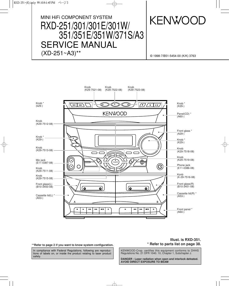
Knob Knob Knob
(K29-7521-08) (K29-7522-08) (K29-7523-08)
K b * I\ - """""""""""""""""" \ / - K b *
«2%» TEED mu- 1 ($91
KENWOOD kiPaneKCD)
(A60-)
Knob
(K29-7512-08)
I Front glass
' (A29-)
Knob
(K29') ,-Knob
/\ (K29-)
\ / K£2095) 7513 08 Km"
( - - ) C) (3 fRJ (I) (3 V (K29-7518-08)
Micjack

'iflix

\

00+

_ Knob
O {y- A (K29-7519-08)
V R EV

Phone Jack
(E11-0386-08)

(K29-7511-08)

(E11-0387-08) 4C1)
Knob k0 0
I

Knob \

(K29-7515-08)

Front glass(L) \

(810-3450-08)

Cassette |id(L) %
(A53-)

Refer to page 2 if you want to know system configuration.


/ (K-29-7516-08)
Front glass(R)

' (810-3451-08)

Cassette |id(R)
(A53-)

. Front panel
(A60-)

Illust. is RXD-351.
* Refer to parts list on page 38.

in compliance with Federal Regulations, following are reproduc-
tions of labels on, or inside the product relating to laser product

safety.

KENWOOD-Crop. certifies this equipment conforms to DHHS
Regulations No. 21 DFR 1040. 10, Chapter 1, Subchapter J.

DANGER : Laser radiation when open and interlock defeated.
AVOID DIRECT EXPOSURE TO BEAM

fii

Page 2

rx
\/

RXD7251~(K) iutlp 99.108 6:45 PM Nb? 3

RXD-251/301/351/371 S/A3

CONTENTS / ACCESSORIES


Contents
CONTENTS / ACCESSORIES .................................... 2 WIRING DIAGRAM .................................................... 15
EXTERNAL VIEW PARTS DESCRIPTIONS
CONTROLS ......... PC BOARD ..................
BLOCK DIAGRAM .. SCHEMATIC DIAGRAM.
CIRCUIT DESCRIPTION ............................................. 7 EXPLODED VIEW .......
CD MECHANISM OPERATION DESCRIPTION ......... 9 PARTS LIST ................. ..
ADJUSTMENT .......................................................... 11 SPECIFICATIONS ..................................................... 47
Accessories
7777777 FM indoorantennaIII~~~~~~~~~~W ACplugadapmrm

Europe and U.K. Other countries (E03-0115-05)

(T90-0836-05) (T90-0801-05)

:E1E2E3E4T1TZQ1QZ :KIPIY1M1M2M3XIX2X3

Batteries (RS/AA) (2)

9

AM loop antenna (1)

(A70-1260-08)

Use to adapt the plug on the power cord
to the shape of the wall outlet.
(Accessory only for regions where use is

I
I

I

I

I e,»
I

I @l

I

I

I

I

necessar.
(T90-0815-08) I)
Remote control unit (1)
FEOIO EUE 4? I-
gx m o o 3 L. 0
mg Q Eu 5 g 0% I
m 3 o.- I
8 x e > CEO I
a-Ii D 35? I
E 5 E 232 I
0 E L, s w LLIg I
0
Q) @033; 020 W

System configuration

Cautions

SYSTEM MAIN UNIT DESTINATION SPEAKER
XD-301 RXD-301 E3T2X3 Ls-N3o1
xo-301 E RXD-301 E E4 LS-N301
XD-301W FtXD-301W 02 Ls-N301
XD-351 RXD-351 E1T1 Ls-N351
xo-351 RXD-351 M1 x1 Y1 Ls-N371
XD-351 E RXD-351 E E2 Ls-N351
XD-351W RXD-351W Q1 Ls-N351
XD-A3 RXD-A3 K1 P1 LS-N351
xo-371s RXD-37t 3 M2 LS-N371
xo-251 RXD-251 M3X2 Ls-N351

Operation to reset

The microcomputer may fall into malfunction (impossibility to oper-
ate, erroneous display, etc.) when the power cord is unplugged
while power is ON or due to an external factor. In this case, execute
the following procedure to reset the microcomputer and return it to
normal condition.

Press the "POWER" key while holding the Stop (I) key of
the CD section pressed, to switch off the power, and then
switch the power on again after a few seconds.

0 Please note that resetting the microcomputer clears the contents
stored in and returns and to condition when it left the factory.

Page 13

RXD7251~(K)iut1p 99.108 6:46 PM \°-/ 28 /\

RXD-251/301/351/3718/A3

ADJUSTMENT

CASSETTE DECK SECTION

INPUT OUTPUT CASSETTE TAPE ALIGNMENT ALGN FOR FIG
SETTINGS SETTINGS DECK SETTINGS POINT .

NO. ITEM

Unless otherwise specified : each ; switch should be set as follows : ost = 0.775V
BEAT SW : OFF
|. Cassette mechanism section (REC/PB head adjustment)

Demagnetize the REC/PB
REC/PB head, head by head eraser. Clean

. . P FF,
Demagnetization owerO . erase head. the REC/PB head, erase
[1] . 7 ~ demagnetization, . .
and cleaning cleaning play capstan, pinch head capstan and punch
roller roller with a cotton swab
immersed in alcohol.
In a setting wher the output
is maximized, adjust the
azimuth adjustment screw
MTT7114, Azimuth so that the Lissajous figure
REC/PB head TCCV153 . appearing on the oscilloscope
I2] azimuth 86071727 (A) PLAY adjusténent screen comes near to a line
10 kHz, 710dB 5° W sjanled45° Note :The head
should be installed in such a
manner that it approaches the
tape face.
II. PC board adjustment
/\ $22.11;; Adjust so that Frequency is
K / < 1 > Tape speed 80071727 (A) PLAY SFR201 3 kHz at the center of the
3 kHz, .4 dB Iape'
T607120 Approx. 75dBm
< 2 > Playback level 315 Hz OdB (A) PLAY -:/\- reference level
Put standard
R d' | I test tape D bb' d
ecor mg eve 00120) u mg an 7
into B deck. playback. Approxt 5dBm
< 3 > (A)
-2<- reference level
Put standard
blank tape
into A deck.

INSTRUMENTS CONNECTION

Oscilloscope ACvoltmeter

Frequency counter

0 man

a l.

Elm
El
Elm
a
v

DOOO~
u

P|N2

IC401
MAIN UNIT

13

Page 20

INIZP 99.1086:59PM 592

PC BOARD (Component side View)

DISPLAY UNIT

HAY/PAUSE
AMS- 673 AMS+ DISC snap DISCl mscz mscz OPEN/CLOSE STOP cm
E R674 R575 R677 R678 R671 3 1
2
H 2
601
° N * C605 8 CN
fi' In 5 EE 3 1
8 8 8I | I I ENE}
m: N 5 ma 5:" §| .3 2 s:
E: E? . I: I:
. :52
. . .2
3 .E 1
G.
fi. >501 LPGDZ LP603
.2§6.5..
_J§63__ :
1 mm 32 :2 m 2 m
,0 w .0 m
.- z a: a:
REMOTE BO E
senson
/\ 1
x 2 4 i
n an
'I' 1 1 11M: MODE AUTO/MONO AUTO mesa
C316
7 a | |
5 R320. 3 R614
re a 5 0
I I "I '
z m m I " C314 i
El El 0303 @ g : :
a 2 -
R327 1 SJ R646
C305 BAND 1 6
q q .
5 R315 - 5612 él § él fig .5 cam E can
" meme
mm m; Wm M
- x TUNERDOWN
2' El N C302 MICVOLUME
EI 2|
m
A s s
'1" (Elm g g
N
a|
u
- - (501
6
MIC2 MlCl DNES
7

21

22

Refer to the schematic diagram for the value of resistors and capacitors.

K

\/