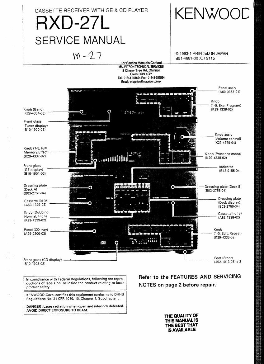
Kenwood RXD 27 L Service Manual

This is the 110 pages manual for Kenwood RXD 27 L Service Manual.
Read or download the pdf for free. If you want to contribute, please mail your pdfs to info@audioservicemanuals.com.

Page: 1 / 110
left right
Kenwood RXD 27 L Service Manual

Extracted text from Kenwood RXD 27 L Service Manual (Ocr-read)


Page 1

RXD-27L KENWOOE

SERVICE MANUAL

WI 17 © 1993-1 PRINTED lN JAPAN
851-4681-OOIO) 2115

For

SamoaManualsmniafl
MAURITRON TECHNlCAL SERVICES
8 Cherry Tree Rd, Chinnor
Oxon OX9 4OY
Tel1- 018M»351694 Fax1- 01844-3525
Email? anqrjfiesiibmauilronmm


. Panel assy
KENJ/OCD "
eeeaqacqegaqfi'fi , ' ' _- lASU-O353-Oll

. Knob
' ll-O, Exe, Program)
IF «294336-02

Knob (Bandl

(K294334433) -'-" I 5153-- m
Frontglass

lTuner display)

(310-1900-03)
...... ragga-513115355 I; Knob assy
. -. (Volumecontrol)
. . (K29~4379-04I
KnobI1-5.R/M ,. ' '
Memory,Ef'iect) . ' -u '1: Knob (P ese 0 )
«294337-02; 3 I- ' me mo 3
II .| (K29-4338-02)
Frontglass '
. Indicator
l
IgIEO?IZ%:-y-))3l (812-0186-04)

Dressing plate
(Deck Al
(303-27 57-04)

---Dressing plate (Deck Bl
IEO3<2758~04I

Dressing plate
IDeck display)
(8034759414)

Cassene lid (Al
IA53-1329-02)

Knob IDubeng Cassette lid {8)

Normal, High)

(Km-433902) (A534328-02)
_. 2°.E"?'f°.fl°°.'=. . '

Panel (CD rray) .. , . . .. . ,\m Knob

(A29~0200'03l _ " I---- (1-0, Edit, Repeat)

0 (KN-433502)
[I
eél

______I
From glass (CD display) . Foot (Front)

lBlO-1903-03) IJ02-1013-05l x 2

Refer to the FEATURES AND SERVICING
NOTES on page 2 before repair.

in compliance with Federal Regulations, following are repro-
ductions of labels on, or inside the product relating to laser
product safety.

KENWOOD-Corp. certifies this equipment conforms to DHHS
Regulations No. 21 CFR 1040. 10, Chapter 1, Subchapter J.

DANGER: Laser radiation when open and interlock defeated.
AVOID DIRECT EXPOSURE TO BEAM.

THE QUALITY OF

THIS MANUAL IS

THE BEST THAT
IS AVAILABLE

Page 2

RXD-27L

CONTENTS/ FEATURES AND SERVICING NOTES

CONTENTS

FEATURES AND SERVICING NOTES
EXTERNAL VIEW : REAR PANEL .
ACCESSORIES .
CONTROLS ..
REMOTE CONTROL ..
DISASSEMBLY FOR REPAIR .
BLOCK DIAGRAM
CIRCUIT DESCRIPTION
DECK SECTION ............
RECEIVER, GE SECTION
OPERATION OF TIMER ..........

FEATURES AND SERVICING NOTES

- The features of, and servicing notes for the MIDI

system are described below.

(1) The tuner. amplifier, GE, decks and CD blocks are
integrated. so pay attention to the following wiring
layout of the decks and CD blocks :

- Separate the 6-wire cable of connector CN7 (+3)
and WH1 on the CD unit (X32-l.

v Separate the wires for connector CN2 from the
wires for connector CN3 on the CD unit (X32-I in
accordance with first wiring pattern.

0 The lead wires of cassette decks, the WHI lead
wires that are connected from the X28- unit to the
X25- (8/2) unit. and the WH3 lead wires that are
connected from the X32- unit to the X25- W2) unit
must be kept apart from the volume control unit
IXl4-, 8/5) and the MIC unit (X14-, DIS).

- The secondary wirings of power transformer must
be kept apart from the Dolby IC (lC20) on the X28-
unit and the 13 parallel lead wires that are con-
nected from the volume control unit 004-, 3/5) to
the main unit (X09-, CN4).

(2) To listen to a selector otherthan the deck and CD
blocks using a timer, remove the cassette tape and
CD disc.

(3) A TIMER PLAY key is not provided on the deck
block. The TIMER PLAY mode can be entered
when the TIMER REC LED indicator is not on.

ADJUSTMENT.. .......... 35, 38~40, 43, 45, 4e
REGLAGE .36, 38, 39, 41, 44, 45, 47
ABGLEICH .. ....37, 33, 39, 42, 44, 45, 47
WIRING DIAGRAM .................................................
PC BOARD ICOMPONENT SIDE VIEW)

............ 49-52, 69-72
............ 53~68, 73~7e

S

SCHEMATIC DIAGRAM
EXPLODED VIEW
MECHANISM

UNIT
PARTS LIS ".83
SPECIFICATIONS ....BACK COVER

(4) The microprocessor is powered, if the power cord
is connected to an AC outlet. When soldering and
replacing parts, disconnect the power cord from
the outlet.

(5) The CD mechanism has no transport screw. Dur-
ing unit transport or movement, return the mecha-
nism to the initial setting before Switching the
power OFF.

Note related to transportation and
movement
When this unit is to be transported or shifted, carry out

the tollomng procedure. (for prorecxion oi the internal

mechanism)

1. Turn the power ON without putting a disc in the
unit.

2. Wait several seconds. Ind chock that the display
shown below appears.

3. Turn the power OFF.

(6) Recording on metal tapes cannot be carried out,

Note 2 Refer to RXD-ZS/ZSL service manual, if need description about item of table.

Item Reference service manual Reference page

CD SECTION TEST MODE P22-27

uPD75212ACW-157 (X32-, ICISI P28, 29

CXATOBIS (X32-, lCiI RXD-ZS/ZSL P30, 31

CIRCUIT DESCRIPTION CXAIZM-S (X32-, lCZ) P32, 33
CXDI 1670 (X32-, IC3I P34-36

TC9237B (X323 ICIII DP-M7730/M6630/M991 P25, 26

DECK SECTION TEST MODE RXD-25/25L P39~45

MECHANISM CD MECHANISM RXD<25/25L P72~74
DESCRIPTION DECK MECHANISM X-722 PIS-27

Page 27

9-3. Pin function

CIRCUIT DESCRIPTION

RXD-27L

Pin No. Pin name lIO Name Description
1-4 S3~0 O d-a d-a segment dnve/key scant
5-8 Poo-03 KEG-3 Key-matrix. key return Input.
9 P10 HEMlN Remote control input.
10 P11 E Backup detection (1. : BACKUP),
11 P12 m Stereo broadcast detection lL : STEREO).
12 m 753 Station detection (L : STATlONl.
13 P20 CLK Control PLL IC lLM7001l clock
14 P21 0 DATA Control PLL IC (LM7001) data.
15 P22 ST Control PLL lC lLM7001l strobe
16 P23 M_UTE Mute signal out lL ; MUTE ON).
17 P30 l/O BUSY System control signal input/output (BUSY).
18 P31 SDATA System control signal input/output (DATA),
19 P32 | PROTECT Protection signal input lH : PROTECTIONL
20 P33 MBUSY GE u-ccm (M50940) BUSY input,
21 P60 0 MREO GE u-com (M50940) DATA REQUEST output.
22 P61 MRESET GE imam (M50940) RESET (L to H : RESETL
23 P62 l CH-SPACE lnstitite Channel space (FM L : 100k, H : 5010
24 P63 TST Strobe for TC9162/TC9163.
25 P40 TDT Data for TCSISZ/TC3163 (H : Power 0M
26 PM 0 TCLK Clock for TC9162ITC3163.
27 P42 SPRLY Control output relay lH : Relay ON).
28 P43 MONO Monoral control (H * Monol,
29 FPO Not used (Openl.
30, 31 X1, 2 l. O _ System clock oscillation (crystal 4.194303MH2).
32 V55 - Power supply (GND),
33. 34 XTl. 2 l, 0 Not used lXTl : GND. XTZ : Open).
35 P50 LOAD Strobe for MSC7112.
36 P51 GECLK Clock for NJU7305Ll
37 P52 0 GEDT Data for NJU7305L.
38 P53 POWER Power relay control.
39 W - - Reset lL : RESET).
40-48 T0-8 96-16 Grid control (SG-lGL
49 T9 - Not used.
50 PH3 TMUTE Tuner mute signal out (L : MUTE ON).
51 PHZ O - Not used (OpenL
52 PH! VOL UP Electrically driven volume control lH : VOL UPL
53 PHO VOL DOWN Electrically driven volume control (H : VOL DOWN).
54 511 I l«segment drive.
55 510 k k-segrnent drive/key scan.
56 VLOAO _ _ Pull-down for FL (-30%
57 Vens Predriver for FL.
58-63 59-84 0 i~e j-e segment drive/key scan.
64 Vuo - - Power supply (+5Vl.

27

n-

Page 88

E___.E_£__ as _E_ a

g... m m rum .i'ao 05cm"
9. 11: AL

nusa .
07 02:

us In WI
m um

:50
{36le

an as!

:2:
use

Fawn AMP

an
n . r
i m4

cm mu
5E LEVEL .
{ca

YESHNC
7m

4

vi!

nmsm uuumx
Anna: Sui

assisraa unwan-
Ant-Lon 5w

cm:
zzar

cm
i,
cm Han!

cm a."

ce veitmeier, Vaiues may vary slighiiv due to variations between individual instruments CAUTION : For continued safety, repiace safety critical
list). A indicaies safety cniicai components. To reduce the r
zoltmétre a haure impedance. Les vaieurs peuvent diffarer iégéramem du fair das vari- out (exposed pans are acceptably insulated from we supply

3 de mesure individueis.
it einem hoc'nohmigenloltmeter gemessen. Dabex scnwanken die Meawene aufgrund
Ian ccer Gera'fien u.u. gennngQIG-