Kenwood RSG 7 Service Manual

This is the 25 pages manual for Kenwood RSG 7 Service Manual.
Read or download the pdf for free. If you want to contribute, please mail your pdfs to info@audioservicemanuals.com.

Page: 1 / 25
left right
Kenwood RSG 7 Service Manual

Extracted text from Kenwood RSG 7 Service Manual (Ocr-read)


Page 1

RiSG'HK) COVER1,1P( 99.10t300:l7PM y [W 2

STEREO INTEGRATEDAMPLIFIER/TUNER KEN V OOD
R-SG7/SG7G W

SERVICE MANUAL

© 1999-7/B51-5549-00 (K/K) 2299

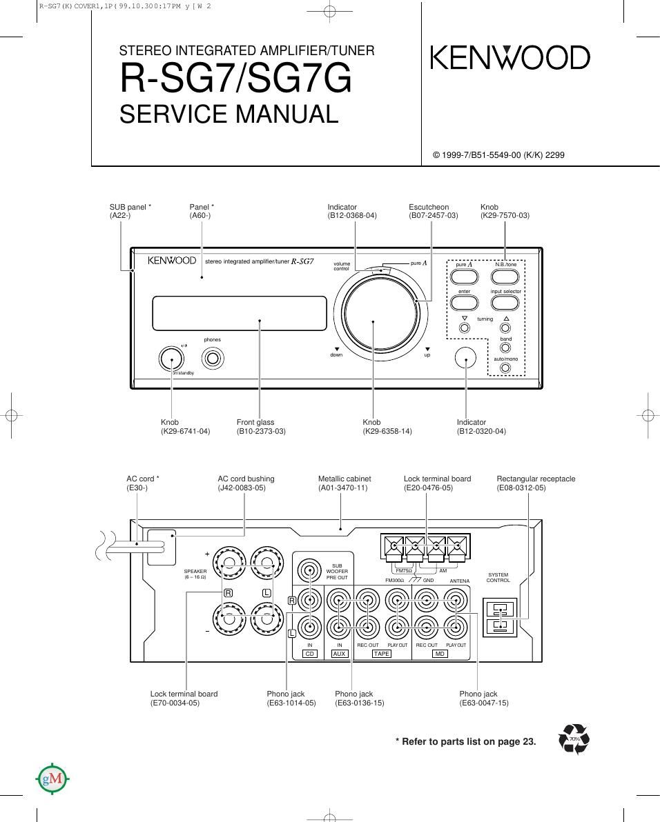
SUB panel Panel Indicator Escutcheon Knob
(A22-) (A80-) (812-0368-04) (807-2457-03) (K29-7570-03)

KENWOOD stereo integrated amplifier/tuner R7567

volume
control

phones

©

N
540
©:@

/ \
K / Knob Front glass Knob Indicator
(K29-6741-04) (B10-2373-03) (K29-6358-14) (812-0320-04)
AC cord AC cord bushing Metallic cabinet Lock terminal board Rectangular receptacle
(E30-) (J42-0083-05) (A01 -347o-1 1) (E20-0476-05) (E08-0312-05)


<
2/? WWW
\ W +
(63 (73) Sue mi
$3537 J % 35555? $
IE] K) rm
3
U U § 6 \ R fl E]
, -@ 9 Q) <9 w J E
IN N REC OLlT PLAY OUT REC OUT PLAV OuT
Lock terminal board Phono jack Phono lack Pnono jack
(E70-0034-05) (E63-1014-05) (E63-0136-15) (E63-0047-15)

* Refer to parts list on page 23. m

Page 2

F\
\/

RiSG7(K) COVER1,1P( 99.10.300:l7FM y [W 3

R-SG7/SG7G

CONTENTS / ACCESSORIES

Contents
CONTENTS / ACCESSORIES .. 2 SCHEMATIC DIAGRAM ., ..... 11
CIRCUIT DESCRIPTION ........... ....3 EXPLODED VIEW ................. 22
ADJUSTMENT.... ....7 PARTS LIST ................................. 23
PC BOARD ......... .. 8 SPECIFICATIONS ..... Back cover
Accessories
( \
..... AM loop antenna (1) .......................................... FM indoor antenna (1) Batteries (Re/AA) (2)
l (T90-0833-05) (T90-0801-15) : M
5 AM loop antenna stand (1) (T90-0809-05) : ET
(J19-3645-05) 2 0

Audio cords (2) System control cord (1) AC plug adaptor (1)
(E30-0615-05) (E30-2628-05) (E03-0115-05)
l
Remote control unit (1)
(A70-1154-05) : M ....... RC-SE9 _ _
(A70-1155-05) :TE ....... RC-SE9(E) Banery cover (A09 0356 08)
i:
Q %
O 6
O E
3 8
E E
x g
LIJ
II
k 1
Operation to reset
The microcomputer may fall into malfunction (impos- R'SG7
sibility to operate, erroneous display, etc.) when the PP the'powe'r plug Pm theureceptacle,)and then plug
power cord is unplugged while power is ON or due to it in again while keeping the on/standby key pressed.
an external factor. In this case, execute the following
procedure to reset the microcomputer and return it
to normal condition.
0 Please note that resetting the microcomputer clears the
contents stored in it returns it to condition when it left the
factory.
2