Kenwood RDDV 7 L Service Manual

This is the 61 pages manual for Kenwood RDDV 7 L Service Manual.
Read or download the pdf for free. If you want to contribute, please mail your pdfs to info@audioservicemanuals.com.

Page: 1 / 61
left right
Kenwood RDDV 7 L Service Manual

Extracted text from Kenwood RDDV 7 L Service Manual (Ocr-read)


Page 1

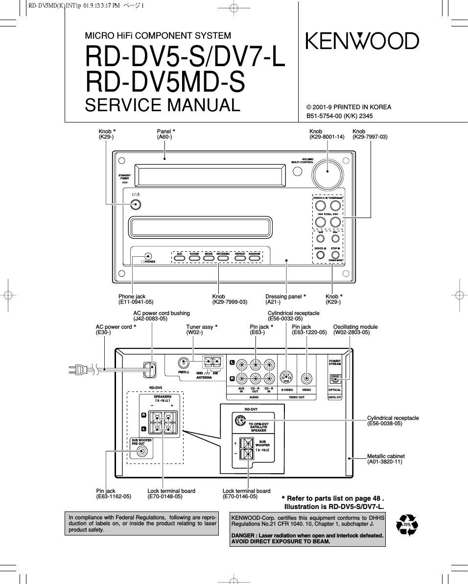
RDeDVSMD(K INTlp 01.9.13 3:17 PM «HAS/1 /\
\/

ERETBWEEEVH KENWOOD

RD-DVSMD-S

SERVICE MANUAL ©2001-9 PRINTED INKOREA

B51-5754-00 (K/K) 2345

Knob * Panel * Knob Knob
(K29-) (A60-) (K29-8001-14) (K29-7997-03)
O Mumcéiri'fi C

snunav
IIIMER

O

lwwcnwnwuiwnnnl
.

aO
fivnoues
O
/\ . .
x / Phone Jack Knob Dressmg panel * Knob *
(E11-0941-05) (K29-7999-03) (A21 -) (K29-)
AC power cord bushing Cylindrical receptacle
(J42-0083-05) (E56-0032-05)
AC power cord * Tuner assy * Pin jack * Pin jack Oscillating module
(E30-) (W02-) (E63-) (E63-1220-05) (W02-2803-05)
.
WI
IE e a Q & © © @ m
- = FWSR GND 47WJ fl 3
ANTENNA 3 © © © 999 O @
,,,,,, 'Z'EVE , , , , , w 25,-: cw svmso mm mm
SPEAKERS AUDIO VIDEO 0|" lltfillALollf

(s-Ian)

Cylindrical receptacle
(E56-0038-05)

SPEAKER

sue wooFEn
PRE our

woonn
1 a asp)

._ Metallic cabinet
(A01 {3820-1 1)

Pin jack Lock terminal board Lock terminal board
(E63-1162-05) (E70-0148-05) (E70-0146-05) -)|- Refer to parts list on page 48 _
Illustration is RD-DV5-S/DV7-L.
In compliance with Federal Regulations, following are repro- KENWOOD-Corp. certifies this equipment conforms to DHHS .
duction of labels on, or inside the product relating to laser Regulations No.21 CFFl 1040. 10, Chapter 1, subchapter J. 7004
product safety. I
DANGER : Laser radiation when open and interlock defeated.

AVOID DIRECT EXPOSURE TO BEAM.

l l 4

Page 2

r\
\/

RDPDVSMD(K)INT1p 01.9.13 3:17PM «Ks/2

RD-DV5-S/DV7-L/DV5MD-S

CONTENTS / ACCESSORIES / CAUTIONS

Contents
CONTENTS / ACCESSORIES / CAUTIONS
DISASSEMBLY FOR REPAIR ......................
BLOCK DIAGRAM ...........
CIRCUIT DESCRIPTION.

makibfcam

ADJUSTMENT ...... PARTS LIST ............
WIRING DIAGRAM SPECIFICATIONS
Accessories

f

PARTS DESCRIPTIONS.
PC BOARD ......................
SCHEMATIC DIAGRAM ..
EXPLODED VIEW ...........


FM indoor antenna (1)
(T90-0855-05)

AM loop antenna)
(Tim-085205)

Batteries (R6/AA)(2)

Remote control unit(1)
(A70-1521-05): M
(A70-1522-05): TE
(A70-1524-05): M2X2V2

SCAT plug adaptor for TV(1)
(For EUROPE and UK.)
(ESQ-001205)

K

System configurations

SYSTEM MAIN UNIT DESTINATION SPEAKER SP CORD PARTS No. REMOTE MODEL

Cautions

Video cordl1)
(E30-7226-05)

Speaker cord(2)

Cushion for satellite speaker(4)
(W01-1178-08)

Feet for speaker(4)
(J02-0034-08)

AC Plug Adaptor (1)
(E03-0115-05)

Remote controller

Use to adapt the plug on the
power cord to the shape of the
wall outlet.

(Accessory only for regions where
use is necessary.)

CONTOROLLER NAME MAIN UNIT DESTINATION
A70-1521-05 RC-M051 3 RD~DV5MD-S M
A70-1522-05 RC-F0504E R D-DVS-S TE
A70-1524~05 RC-F0505 RD-DV7-L M2X2V2
A70-1525-05 RC-F0505E RD-DV7-L T2E2

Operation to reset

The microcomputer may fall into malfunction (impossibility to
operate, erroneous display, etc.) when the power cord is unv
plugged while unit is ON or due to an external factor. In this
case, execute the following procedure to reset the micro-
computer and return it to normal condition.

Unplug the power cord from the power outlet
then, while holding the STOP l [TUNING MODE
key depressed, plug the power cord again.

0 Please note that resetting the microcomputer clears
the contents stored in and it returns to condition
when it left the factory.

The marking afproducts using lasers (For countries other than U.S.A., U.S.-Military and Canada)

CLASS 1
LASER PRODUCT

vIsIaLE LASER RADIATION
WHEN oPEN. Do NOT
STARE INro BEAM.

CAUTION
VISIBLE LASER
RADIATION WHEN OPEN.
AVOID EXPOSURE TO BEAM.

The marking this product has been
classified as Class I. It means that
there is no danger of hazardous rae
diation outside the product.
Location: Back panel

Inside this laser product, a laser die
ode classified as Class 2 laser rae
diation is contained as alerted by
the internal caution label shown
above. Do not stare into beam.
Location: DVD laser pickeup unit
cover inside this product

Inside this laser product, a laser die
ode classified as Class 3B laser rae
diation is contained as alerted by
the internal caution label shown
above. Avoid exposure to laser
beams.

Location: MD laser pickeup unit
cover inside this product

8?

Page 13

RDeDVSMD(K)INT1p 01.9.13 3:17 PM N? 13

RD-DV5-S/DV7-L/DV5MD-S

CIRCUIT DESCRIPTION

Low reflection disc

Step No. Setting Method Remarks Display

Step 1 Test mode STOP state I I 5 0000 e 00 I
Step 2 Press the SKIP DOWN(K<) button six times. MANUAL adjustment menu [A M N U A A J S T A]
Step 3 Press once the MD PLAY button. Initial setting a) Temperature measuring mode [T M P : A AA A A A]
Step 4 Press once the SKIP DOWN(I<<) button. Laser ON [ L O N : 777777 ]
Step 5 Press once the SKIP DOWN(I<<) button. Innermost periphery move -> Tracking ATT (E signal) setting [ P E G : AAAOOO]
Step 6 Press once the SKIP DOWN(I<<) button. Tracking A'l'l' (F signal) setting [ P F G : AAAOOO]
Step 7 Press once the SKIP DOWN(I<<) button. Indication ot tracking EFMIO measurement (pit section) [ P M I : AAA _ A A]
Step 8 Press once the SKIP DOWN(I<<) button, Focus ATT (A signal) setting [ L A g : AAAOOO]
Step 9 Press once the SKIP DOWN(I<<) button, Focus ATT (B signal) setting [ L B g : AAAOOO]
Step 10 Press once the SKIP DOWN(I<<) button. Outside periphery move a) Track closs setting [ G C G : AAAOOO]
Step 11 Press once the SKIP DOWN(I<<) button. Tracking A'l'l' (E signal) setting [ G E G : AAAOOO]
Step 12 Press once the SKIP DOWN(I<<) button, Tracking A'l'l' (F signal) setting [ G F G : AAAOOO]
Step 13 Press once the SKIP DOWN(I<<) button. Indication of tracking EFMIO measurement (groove section) [ G M l : AAA A A A]
Step 14 Press once the SKIP DOWN(I<<) button. Focus A'I'I' (A signal) setting [ L A G : AAAOOO]
Step 15 Press once the SKIP DOWN(I<<) button. Focus A'I'I' (B signal) setting [ L B G : AAAOOO]

8. TEST-PLAY mode

- It the MD STOP button is pressed twice while the MANUAL adjustment menu is displayed, the state is changed to the TEST mode
STOP state.

step No. Setting Method Remarks Display
Step 1 Test mode STOP state [ t s mOOOO e 00 ]
Step 2 Press once the SKIP UP(>>1)button. [T E S T A P L A Y A]
Press MD PLAY button.
Ia BEDS C 0000]
/\ Step3 Press the STOP button. [TESTAP LAYA]
/
\ Step 4 Press once the MD PLAY button. During search the search output is set to H and it is
returned to "L when continuous playback is started.
ContInuous playback (groove section) (Address + C1 error indication)
Step 5 Press once the MD STOP button. TEST-PLAY menu [T E S T A P L A Y A]

- It the MD STOP button is pressed while the TEST»PLAY menu is displayed, TEST mode STOP state is set.
- It the MD PLAY button is pressed while the TEST-PLAY menu is displayed, continuous playback is started from the current pickup position.

- DEED : Adress, OOOO : Error late

9. TEST-REC mode

Step No. Setting Method Remarks Display
Step 1 Test mode STOP state [t smOOOQ e 00]
Step 2 Press the SKIP UP(>H)button twice. [T E S T A R E C A A]

Press MD PLAY button. I

I a DUDE D W WW I

Step3 Press the STOP button. [T ESTARECAA]
Step 4 Press once the MD PLAY button. During search the search output is set to H, and it is

Continuous playback returned on "L" when continuous playback is started. (Addresst-

(groove section) C1 error indication) [ a [EDD p w VV ]
Step 5 Press once the MD STOP button. TEST-REC menu [T E S T A R E O A A]

- It the MD STOP button is pressed while the TEST»PLAY menu is displayed, TEST mode STOP state is set.
- It the MD PLAY button is pressed while the TEST-REC menu is displayed, continuous record is started from the current pickup position.
- It the (») or (44) button in remote controller is pressed in TEST-REC mode and continuous record mode,
the laser record power changes.
(Sen/o gain changes also according to the record power.)
- DEED : Adress, VV : Laser power cord

10. EJECT mode

step Na. Setting Method Remarks Display

Step 1 Test mode STOP state

Step 2 Test mode EJECT state Eject of MD disc [A A E J E C T A A A]
Step 3 Press SKIP UP(>H) button. Temperature standard value setting. [TEMP 00 O O ]
Step 4 Press STOP button. [ _ , EJECT. L A 7]

~OO: Measurement value, 0 0: Setting value.

13