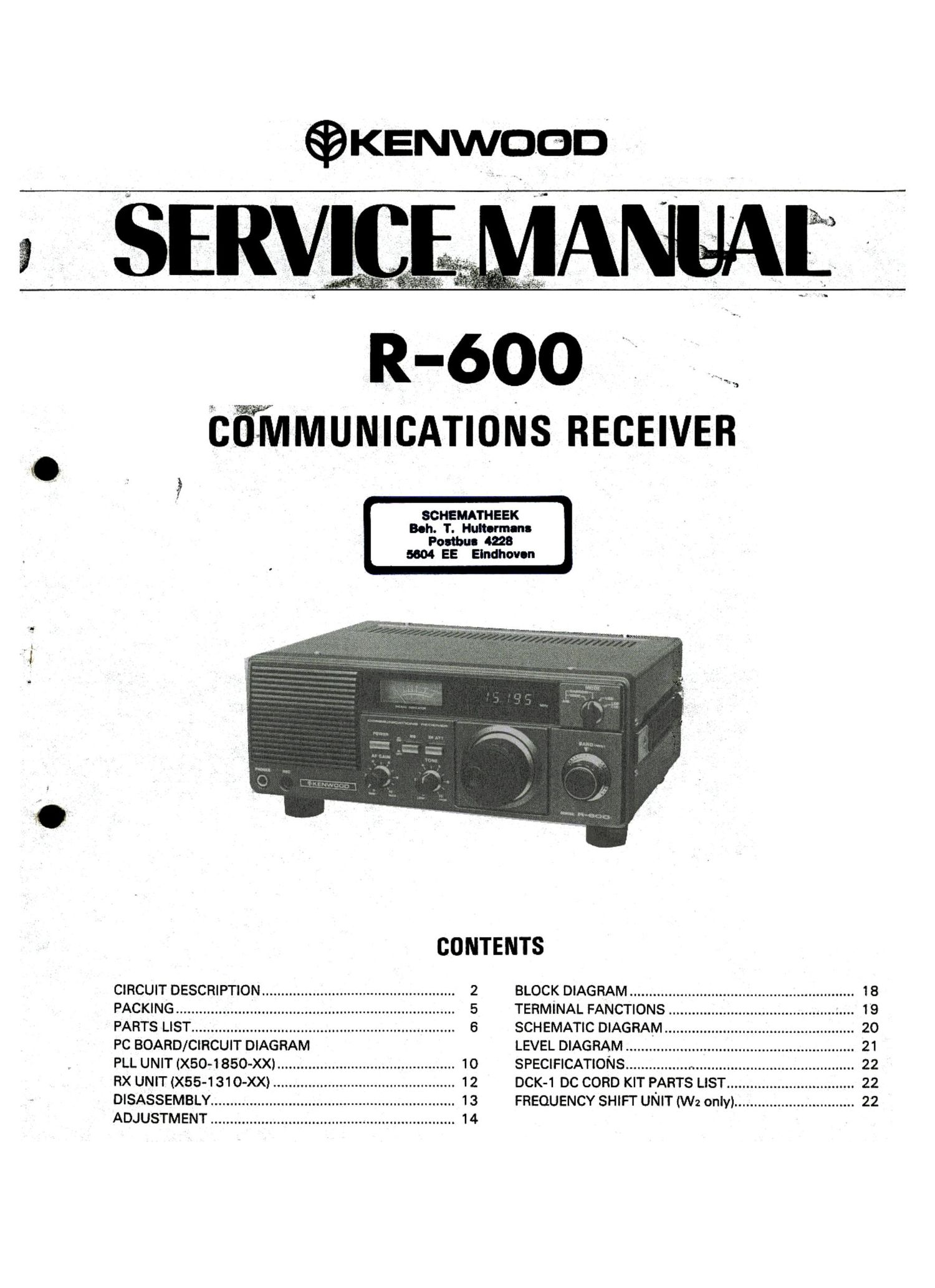
Kenwood R 600 Service Manual

This is the 23 pages manual for Kenwood R 600 Service Manual.
Read or download the pdf for free. If you want to contribute, please mail your pdfs to info@audioservicemanuals.com.

Page: 1 / 23
left right
Kenwood R 600 Service Manual

Extracted text from Kenwood R 600 Service Manual (Ocr-read)


Page 1

© KENwooD

h,

R-bOO

CWMMUNICATIONS RECEIVER

SCHEMATHEEK
Bah. T. Hultormans
Posthu- 4228

5604 EE Elndhovon
CIRCUIT DESCRIPTION .................................................. 2 BLOCK DIAGRAM .......................................................... 18
PACKING ........................................................................ 5 TERMINAL FANCTIONS ................................................ 19
PARTS LIST .................................................................... 6 SCHEMATIC DIAGRAM ................................................. 20
PC BOARD/CIRCUIT DIAGRAM LEVEL DIAGRAM ........................................................... 21
PLL UNIT (X50-1850-XX) .............................................. 10 SPECIFICATIONS ........................................................... 22
RX UNIT (X55-1 310-XX) ............................................... 12 DCK-1 DC CORD KIT PARTS LIST ................................. 22
DISASSEMBLY ............................................................... 13 FREQUENCY SHIFT UNIT (W2 only) ............................... 22

ADJUSTMENT ............................................................... 1 4

Page 2

CIRCUIT DESCRIPTION


is" eneral coverage, triple conversion
receiver with a fi x, econd, and third intermediate fre-
quency of 40.455 MHz. 10.455 MHz, and 455 kHz. It is
provided with two antenna input terminals which are com-
mon to all bands. One terminal is provided for a low-Z (5052)
antenna. and the other is for a high~Z (50052) antenna. The
antenna input signal flows through a 100 mA fuse and a
switchable 20 dB RF attenuator, and then enters the Band
Pass Filter (BPF) group. A separate BPF is provided for each
of six bands; 0.15 to 1 MHz. 1 to 2 MHz. 2 to 4 MHz. 4 to 8
MHz. 8 to 17 MHz. and 17 to 30 MHz. A low pass filter
common to all bands above 2 MHz is used to reject unwant-
ed broadcast band interference (L39, 40, 41).

Exiting the BPF's, the signal flows through 01, a
33K73(GR) RF amplifier operating in the 150 kHz to 30
MHz range, with approximately 15 d8 gain. and then
through a 40.455 MHz i-f trap. The signal is buffered by 02,
a 28C1815(Y) emitter follower, and then enters the first
mixer. 03 and 04, two 38K73(GR) FETs constitute a ba-
lanced mixer in which the incoming signal is mixed with the
VCO (voltage-controlled oscillator) output from the PLL
(phase-locked loop) circuit to produce the first i-f signal at
40.455 MHz. The first i-f signal is filtered through T4 ~ T7.

The signal then enters 05 and 06, 23K19(GR), the se-
cond balanced mixer. Here, the signal is converted to the
second i-f at 10.455 MHz by a mix with the 30 MHz HET
(heterodyne) signal from the PLL circuit.

After passing through Fl, a 10.455 MHZ ceramic filter.
the second i-f then enters 07, 38K73(GR), the third mixer.
Here, the signal is converted to the third i-f at 455 kHz by
mixing with the 10 MHz HET output from the PLL.

This third i-f signal flows through the noise blanker gate
013. 014. 181587 diodes, then F2 (6 kHz) or F3 (2.7 kHz)
455 kHz ceramic filters. The noise blanker. which is de-
signed to operate on ignition noise and similar pulse-type
noises, samples the i-f signal from 07 through a tap on the
secondary of output transformer T10. All transistors in this
circuit are ZSC1815(Y). 022 buffers the H signal for differ-
ential amplifiers 023, 24. 25 amplifies this for detectors
D28, 29 1N60s. The detector output is DC amplified by
026 to drive the noise blanker gate diodes D13, 14. D30,
MV-13 varistor, breaks-over at noise blanker switch ON for
pulse~type signals. 027 is the noise blanker AGC. which al-
lows this circuit to differentiate between signal (slow rise-
time) and unwanted noise (fast rise-time). Filter output is
amplified by 08 and 09, 38K73(GR), the two-stage third i-f
amplifier, The amplifier output enters either the AM or 888
product detectors.

The AM Detector D25. 1N60, receives its signal
through buffer amplifier 010, 2'SC1815(Y) and exits
through emitter follower 011, 28C2240(GR). For 888 re-
ception, the i-f signal is product-detected by diodes D19 ~
22. 1N60's. Carrier is developed by oscillator 016.
2801 815(Y) and buffered by 017. 28C1815(Y). LSB (lower
sideband) shift is provided by switch transistor 015.
25C1815(Y). AGC is detected by diodes 026. 27. 1 N605.
and is amplified by 018, 2801815(Y) (for 01. 8. 9) and
further amplified (for 01. 3, 4 and 7) by 019, 28K19(GR).
020. 28A1015 is the S-meter amplifier. The AGC time-
constant is increased in the 888 modes by switch transistor
021. 2801815(Y). which adds C147 (1 uF) and F1139 (10

kg) to increase the AGC hold-time.

in AM wide reception. F2 (6 kHz) is used. while F3 (2.7
kHz) is employed for AM narrow and 383 mode reception.
The choice of detectors and filters is diode-switch selected
at mode change.) 888 product detector output is switched
by D23. AM detector output by D24. both 1S1555's. Filter
F2 is switched by D15 and D17, 181007s, while F3 is
switched by D16 and D18. 1815878.

The detector outputs are amplified by 012.
2SC2240(GR). This signal proceeds through the Tone and
Gain controls before being amplified by 014, HA1368R
power amplifier. The output of this last stage drives the
Speaker or phones. Additionally, the output of 01 2 is further
amplified by 013. 28C2240(GR). which provides a 300 mV
(nominal) signal to the Record terminal.

028, 2801957(Y) is a 12 volt ripple filter, and 029.
NJM78M09A is the 9 volt AVR (automatic voltage regula-
tor). These stabilize the receiver DC voltages form the main
power supply on the PLL unit. The 9 volt output line is also
returned to the PLL unit. - '

Electrical Paformance

Item Rating
Nominal center frequency 455 kHz
6 dB band width :3 kHz or more
(from 455 kHz)
50 dB band width :9 kHz or less (from 455 kHz)
Ripple (within 455 :2 kHz) 2 dB or less
Insertion loss 6 dB or less
Guaranteed attenuation 60 dB or more
(within 455 i 100 kHz)
I/O matching impedance 2.0 k!)

Table 1 Ceramic filter (L72-0319-05, RX UNIT F2)

Electrical Paformance

Item Rating

Center frequency 10.455 MHz :I: 50 kHz
(3dB band width center point)
3 dB band width 150 :40 kHz
20 dB band width 380 kHz or less
Insertion loss E1 9 dB or less

Formula 20 log 3-52-
Spurious' attenuation 40 dB or more

(within 10.455 :2 MHz) .
Attenuation at 9.545 MHz 47 dB or more
l/O matching impedance 3309

Table 2 Ceramic filter (L72-0331-05. RX UNIT F1)
AM-W

Electrical Performance

Item Rating
Center frequency 455 kHz 10.6 kHz
6 dB band width 2.8 $0.3 kHz
40 dB band width 5.5 kHz or less
Insertion loss (at maximum output) 6.0 dB or less
Guaranteed attenuation 60 dB or more
(within 455 :100 kHz)
Spurious attenuation
(within 0.1 to 1.0 MHz) 40 dB or more
for 600 to 700 kHz 40 dB or more
l/O matching impedance 2.0 k!)

Table 3 Ceramic filter (L72-0332-05. RX UNIT F3)

833. AM-N